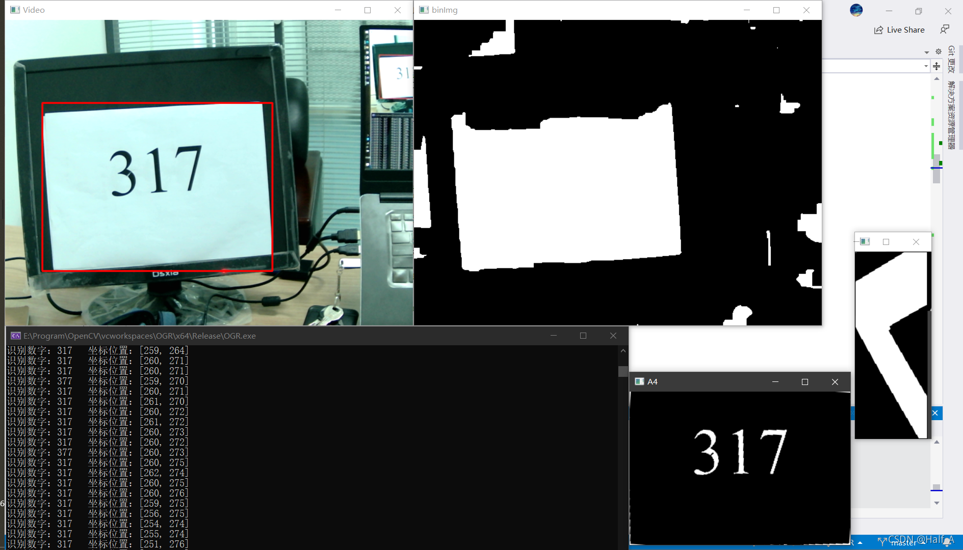
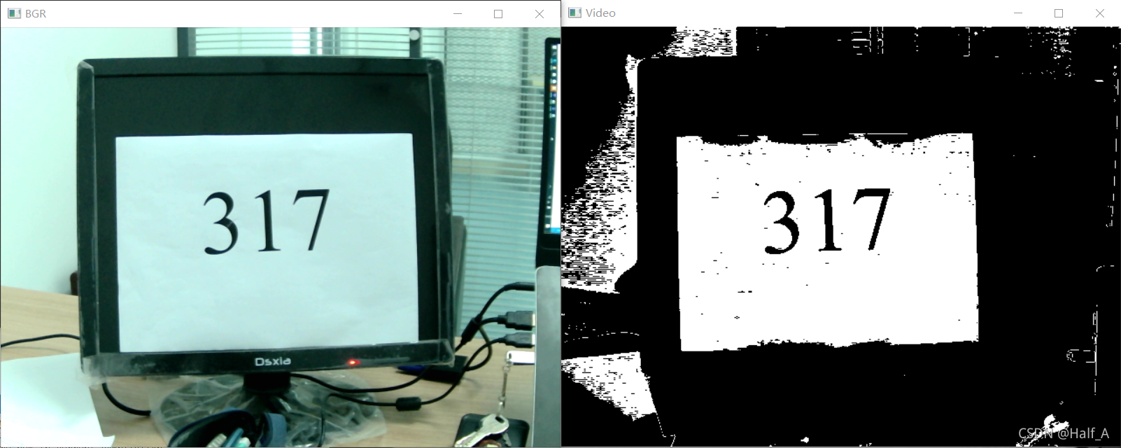
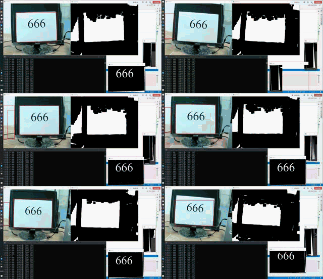
本文的目标是实现识别摄像头图像中的数字 。实际应用场景包括车牌号识别 ,部分竞赛的A4纸打印数字识别 。项目实现结果如下,完整工程文件点此下载 :
摄像头数字识别分为两个步骤:
提取图像中的ROI区域,如截取车牌的矩形区域,或截取A4纸的图像。
对ROI区域进行数字识别。
数字识别相对来说较为简单,先介绍数字识别的方法和原理。
一、数字识别的两种方式
1.1 轮廓提取法
实现思路为对ROI区域进行轮廓提取,然后将所有找到的轮廓与模板逐一匹配识别,相似度大于所设阈值,可视为识别成功。
寻找轮廓所使用的函数为findContours(),利用此函数将所有寻找到的轮廓保存在contours中,然后使用循环画出包围每一个轮廓的最小矩形。
利用每一个小矩形,提取图像中的每一个轮廓图像,将其与模板做差,如果差值越小,说明像素越接近,相似程度越高,以此来实现数字匹配。
1 2 3 4 5 6 7 8 9 10 11 12 13 14 15 16 17 18 19 20 21 22 23 24 25 26 27 28 29 30 31 32 33 34 35 36 37 38 39 40 41 42 43 44 45 46 47 int main () Mat srcImage = imread ("E://Program//OpenCV//vcworkspaces//ogr_test//images//txt.jpg" ); Mat dstImage, grayImage, binImage; srcImage.copyTo (dstImage); cvtColor (srcImage, grayImage, COLOR_BGR2GRAY); threshold (grayImage, binImage, 100 , 255 , cv::THRESH_BINARY_INV); vector<vector<Point>> contours; vector<Vec4i> hierarchy; findContours (binImage, contours, hierarchy, cv::RETR_EXTERNAL, cv::CHAIN_APPROX_NONE); int i = 0 ; vector<vector<Point>>::iterator It; Rect a4rect[15 ]; for (It = contours_rec.begin (); It < contours_rec.end (); It++) { a4rect[i].x = (float )boundingRect (*It).tl ().x; a4rect[i].y = (float )boundingRect (*It).tl ().y; a4rect[i].width = (float )boundingRect (*It).br ().x - (float )boundingRect (*It).tl ().x; a4rect[i].height = (float )boundingRect (*It).br ().y - (float )boundingRect (*It).tl ().y; if ((a4rect[i].height > 80 ) && (a4rect[i].width > 50 ) && (a4rect[i].height < 300 ) && (a4rect[i].width < 300 )) { rectangle (dstImage, a4rect[i], Scalar (0 , 0 , 255 ), 2 , 8 , 0 ); rectangle (binImage, a4rect[i], Scalar (0 , 0 , 0 ), 0 , 8 , 0 ); i++; } } imshow ("dstImage" , dstImage); Mat num[15 ]; int matchingNum = 0 ; int matchingRate = 0 ; for (int j = 0 ; j < i; j++) { a4binImg (a4rect[j]).copyTo (num[j]); imgMatch (num[j], matchingRate, matchingNum); if (matchingRate < 400000 ) { cout << "识别数字:" << matchingNum << "\t匹配率:" << matchingRate << endl; } } system ("pause" ); return 0 ; }
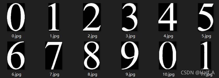
两图像相减之前,需要先制作一张模板,你可以自己在记事本里敲0-9的数字,截图,使用上面的函数imwrite出来一份模板。也可以到我的github中下载 ,其中0.jpg-9.jpg就是模板文件。
1 2 3 4 5 6 7 8 9 10 11 12 13 14 15 16 17 18 19 20 21 22 23 24 25 26 27 28 29 30 31 32 int getPixelSum (Mat& image) int a = 0 ; for (int row = 0 ; row < image.rows; row++) { uchar* current_pixel = image.ptr <uchar>(row); for (int col = 0 ; col < image.cols; col++) { a += *current_pixel++; } } return a; } int imgMatch (Mat& image, int & rate, int & num) Mat imgSub; double min = 10e6 ; num = 0 ; rate = 0 ; for (int i = 0 ; i < 10 ; i++) { Mat templatimg = imread ("E:/Program/OpenCV/vcworkspaces/OGR/images/" + std::to_string (i) + ".jpg" , IMREAD_GRAYSCALE); resize (image, image, Size (32 , 48 ), 0 , 0 , cv::INTER_LINEAR); resize (templatimg, templatimg, Size (32 , 48 ), 0 , 0 , cv::INTER_LINEAR); absdiff (templatimg, image, imgSub); rate = getPixelSum (imgSub); if (rate < min) { min = rate; num = i; } } return num; }
1.2 行列扫描法
此方法主要参考opencv 数字识别详细教程 这篇文章,在此感谢LTG01大佬的无私分享。
基本过程为:
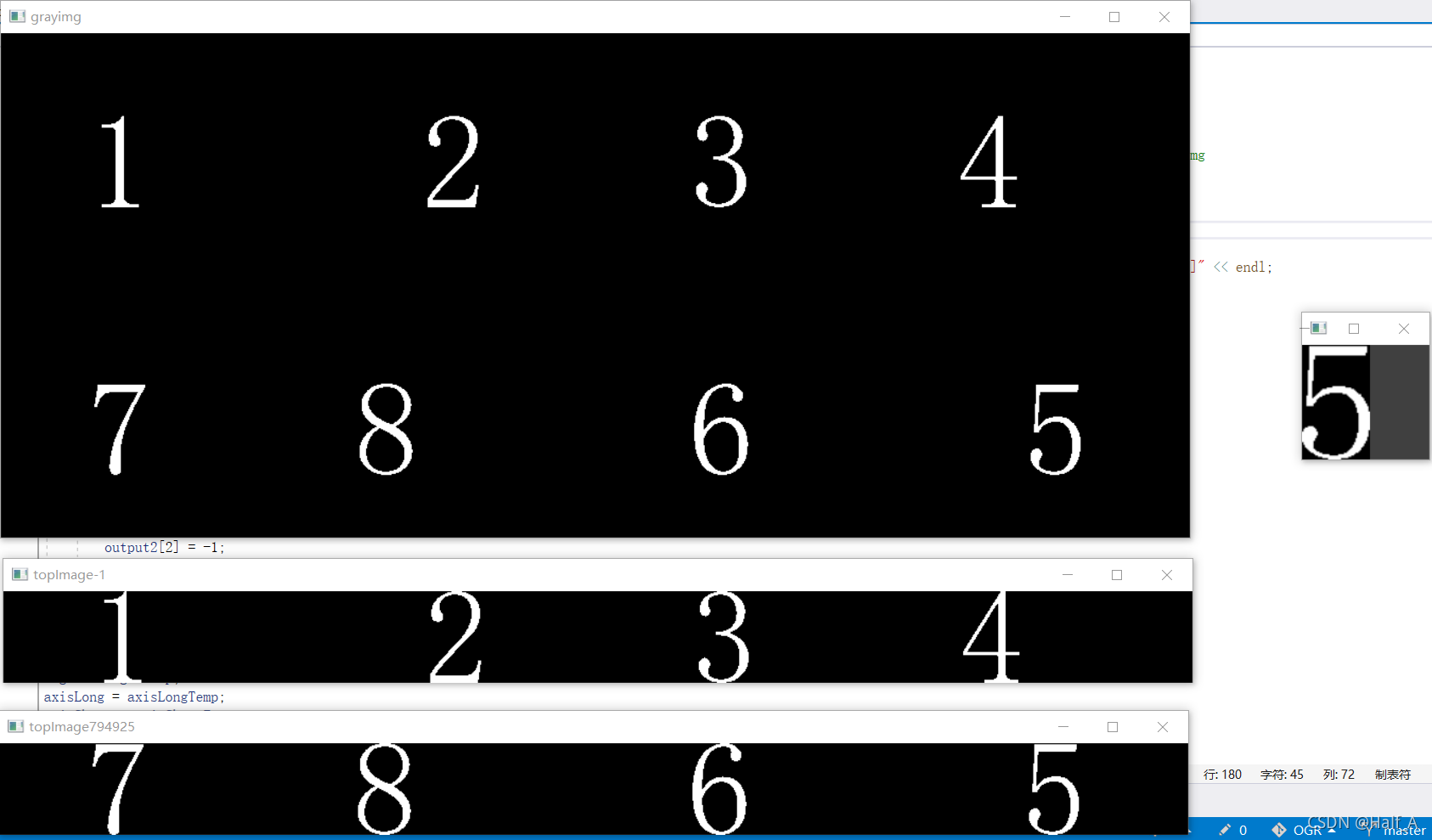
将图像二值化处理,使数字部分为白色,其余部分为黑色。
对一个图像先逐行扫描求和 ,如果第一行像素和为0,则继续向下扫描,直到碰到像素和不为0的行,将行数记下来,此为数字的顶部。
继续向下扫描,此时会从上到下逐渐扫描数字所在的每一行,当行像素和再次为0时,再将行数记录下来,代表已经到了数字的底部,将顶部与底部之间的区域截取出来。
,对截取出来的图像进行逐列扫描求和 ,过程同上,记录出数字的左右列号,根据左右列号即可从刚才截取出的图像中,取出包含数字的最小图像。
利用此最小图像与模板匹配。
1
2
3
4
5
6
7
8
9
10
11
12
13
14
15
16
17
18
19
20
21
22
23
24
25
26
27
28
29
30
31
32
33
34
int main () Mat src = imread ("E:/Program/OpenCV/vcworkspaces/ogr_test/images/txt.jpg" ,IMREAD_GRAYSCALE); Mat grayImage; threshold (src, grayImage, 100 , 255 , THRESH_BINARY_INV); imshow ("grayimg" , grayImage); Mat leftImg, rightImg, topImg, bottomImg; int topRes = cutTop (grayImage, topImg, bottomImg); int matchNum = -1 , matchRate = 10e6 ; while (topRes == 0 ) { int leftRes = cutLeft (topImg, leftImg, rightImg); while (leftRes == 0 ) { imgMatch (leftImg, matchNum, matchRate); imshow ("num" , leftImg); if (matchRate < 300000 ) { cout << "识别数字:" << matchNum << "\t\t匹配度:" << matchRate << endl; } Mat srcTmp = rightImg.clone (); leftRes = cutLeft (srcTmp, leftImg, rightImg); } Mat srcTmp = bottomImg.clone (); topRes = cutTop (srcTmp, topImg, bottomImg); } waitKey (0 ); destroyAllWindows ();; return 0 ; }
有关扫描法识别数字的完整代码见我的Github的scan分支 。
二、提取图像中的ROI区域
提取ROI区域的步骤如下:
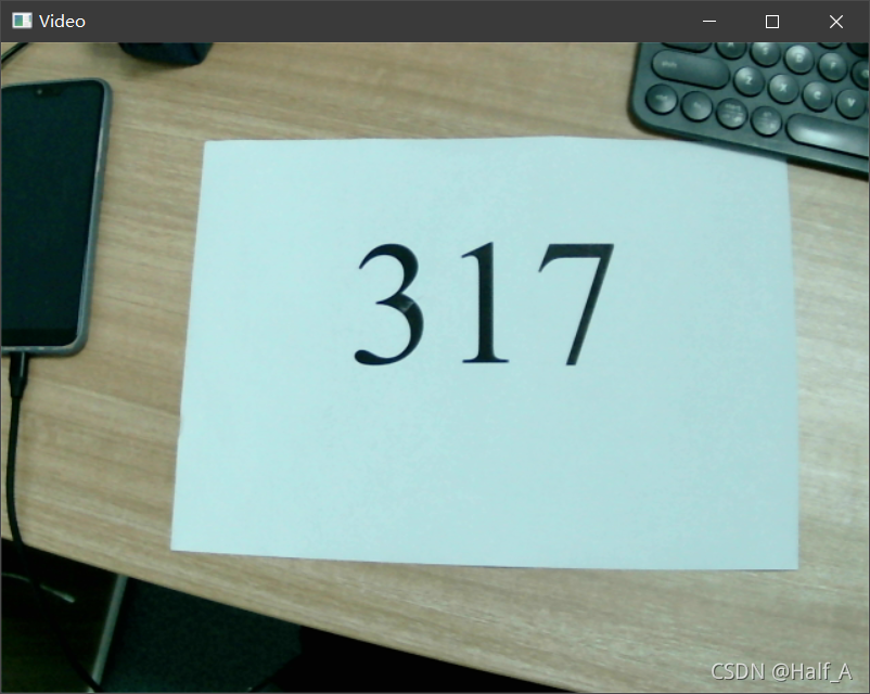
读取摄像头每一帧图像
对图像进行二值化处理
对图像进行形态学处理
设置限制条件寻找目标区域,并框选(这一步是重点)
2.1 读取摄像头图像
摄像头的读取原理在之前的文章中已有介绍《摄像头视频的读取与存储》 。主要使用函数为 capture.read(),此函数用于捕获视频的每一帧,并返回刚刚捕获的帧。示例程序如下:
1
2
3
4
5
6
7
8
9
10
11
12
13
14
15
16
17
18
19
20
21
22
23
24
25
26
int main () VideoCapture capture (0 ) ; int frame_width = capture.get (CAP_PROP_FRAME_WIDTH); int frame_height = capture.get (CAP_PROP_FRAME_HEIGHT); Mat frame; while (capture.isOpened ()) { capture.read (frame); if (frame.empty ()) { break ; } imshow ("Video" , frame); char k = waitKey (333 ); if (k == 'q' ) { break ; } } capture.release (); system ("pause" ); return 0 ; }
2.2 对图像进行二值化处理
通过每个像素的颜色分量将图片进行二值化。正常曝光情况下A4纸的BGR均为215左右 ,车牌的颜色信息大约为B=138,G=63,R=23 。但是在不同环境下颜色信息可能会有偏差,因此需要将条件在一定程度上放宽,再通过其他一些条件来准确查找目标区域。
1 2 3 4 5 6 7 8 9 10 11 12 13 14 15 16 17 18 19 20 21 22 23 24 25 26 27 28 29 30 void binaryProc (Mat& image) unsigned char pixelB, pixelG, pixelR; unsigned char DifMax = 40 ; unsigned char WhiteMax = 50 ; unsigned char B = 215 , G = 215 , R = 215 ; int i = 0 , j = 0 ; for (i = 0 ; i < image.rows; i++) { for (j = 0 ; j < image.cols; j++) { pixelB = image.at <Vec3b>(i, j)[0 ]; pixelG = image.at <Vec3b>(i, j)[1 ]; pixelR = image.at <Vec3b>(i, j)[2 ]; if ((abs (B - pixelB) < DifMax) && (abs (G - pixelG) < DifMax) && (abs (R - pixelR) < DifMax) && abs (pixelB - pixelG) < WhiteMax && abs (pixelG - pixelR) < WhiteMax && abs (pixelB - pixelR) < WhiteMax) { image.at <Vec3b>(i, j)[0 ] = 255 ; image.at <Vec3b>(i, j)[1 ] = 255 ; image.at <Vec3b>(i, j)[2 ] = 255 ; } else { image.at <Vec3b>(i, j)[0 ] = 0 ; image.at <Vec3b>(i, j)[1 ] = 0 ; image.at <Vec3b>(i, j)[2 ] = 0 ; } } } }
2.3 形态学处理
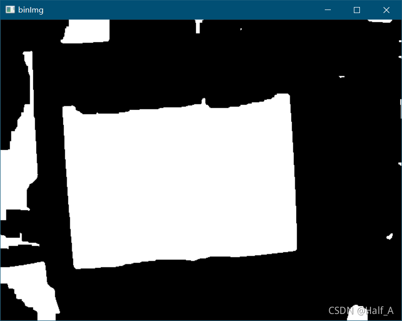
可以看出二值画处理后已经比较明显完整的显示出A4纸区域,但是仍然存在一些噪点,此时进行形态学处理,以消除这些噪点干扰。对图像先膨胀再腐蚀 ,可以填充细小空间,连接临近物体和平滑边界。
1 2 3 4 5 6 7 8 9 10 11 12 13 14 15 16 17 18 19 20 void morphTreat (Mat& binImg) Mat BinOriImg; Mat element = getStructuringElement (MORPH_RECT, Size (5 , 5 )); GaussianBlur (binImg, binImg, Size (5 , 5 ), 11 , 11 ); dilate (binImg, binImg, element); dilate (binImg, binImg, element); dilate (binImg, binImg, element); dilate (binImg, binImg, element); dilate (binImg, binImg, element); erode (binImg, binImg, element); erode (binImg, binImg, element); erode (binImg, binImg, element); erode (binImg, binImg, element); erode (binImg, binImg, element); cvtColor (binImg, binImg, CV_BGR2GRAY); threshold (binImg, binImg, 100 , 255 , THRESH_BINARY); }
矩形窗的大小与膨胀腐蚀的次数会影响处理结果,处理完的结果大致如下。
2.4 设置限制条件寻找目标区域
经过形态学处理,图像中已经可以明显看到A4纸所在的区域,但是图像中仍然不可避免存在其他与A4纸颜色接近的物体,在这里也会显示为白色。这时就需要我们根据A4纸区域的特点设置限制条件,从这些白色区域中找到代表A4纸所在的区域。
在这里我使用的限制条件主要有以下几个:
矩形面积在一定范围内
长宽比A4纸为1.414,一定程度放宽后作为限制条件
短边长度在一定范围内
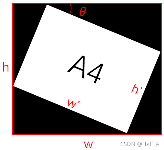
首先寻找图像中的轮廓,利用轮廓面积初步判断,对轮廓面积符合条件的进一步获取其外接矩形。计算此矩形的各个参数(顶点坐标、长宽、面积、倾斜角度等),然后根据限制条件对此矩形进行判别。
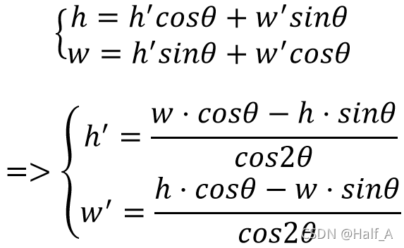
1 2 3 4 5 6 7 8 9 10 11 12 13 14 15 16 void rotateProc (Mat& image, double angle) Mat M; int h = image.rows; int w = image.cols; M = getRotationMatrix2D (Point2f (w / 2 , h / 2 ), angle, 1.0 ); double cos = abs (M.at <double >(0 , 0 )); double sin = abs (M.at <double >(0 , 1 )); int nw = abs (cos * w - sin * h) / abs (cos * cos - sin * sin); int nh = abs (cos * h - sin * w) / abs (cos * cos - sin * sin); M.at <double >(0 , 2 ) += (nw / 2 - w / 2 ); M.at <double >(1 , 2 ) += (nh / 2 - h / 2 ); warpAffine (image, image, M, Size (nw, nh), INTER_LINEAR, 0 , Scalar (0 , 0 , 0 )); }
1 2 3 4 5 6 7 8 9 10 11 12 13 14 15 16 17 18 19 20 21 22 23 24 25 26 27 28 29 30 31 32 33 34 35 36 37 38 39 40 41 42 43 44 45 46 47 48 49 50 51 52 53 54 55 56 57 58 59 60 61 62 63 64 65 66 67 68 69 70 71 72 73 74 75 76 77 78 79 double length, area, rectArea; double long2Short = 0.0 ; Rect rect; RotatedRect box; CvPoint2D32f pt[4 ]; Mat pts; double axisLong = 0.0 , axisShort = 0.0 ; double Length; float angle = 0 ; double location_x = 0.0 ; double location_y = 0.0 ; vector<vector<Point>> contours; vector<Vec4i>hierarchy; findContours (binImg, contours, hierarchy, CV_RETR_EXTERNAL, CV_CHAIN_APPROX_NONE); for (int i = 0 ; i < contours.size (); i++) { length = arcLength (contours[i], true ); area = contourArea (contours[i]); if (area > 2000 && area < 300000 ) { rect = boundingRect (contours[i]); box = minAreaRect (contours[i]); boxPoints (box, pts); for (int row = 0 ; row < pts.rows; row++) { pt[row].x = pts.at <uchar>(row, 0 ); pt[row].y = pts.at <uchar>(row, 1 ); } angle = box.angle; if (angle > 45 ) { angle = angle - 90 ; } axisLong = sqrt (pow (pt[1 ].x - pt[0 ].x, 2 ) + pow (pt[1 ].y - pt[0 ].y, 2 )); axisShort = sqrt (pow (pt[2 ].x - pt[1 ].x, 2 ) + pow (pt[2 ].y - pt[1 ].y, 2 )); if (axisShort > axisLong) { Length = axisLong; axisLong = axisShort; axisShort = Length; } rectArea = axisLong * axisShort; long2Short = axisLong / axisShort; if (long2Short > 1 && long2Short < 1.8 && rectArea > 5000 && rectArea < 300000 && axisShort > 50 ) { rectangle (frame, rect, Scalar (0 , 0 , 255 ), 2 , 8 , 0 ); if (rect.width > 100 && rect.height > 100 && axisShort>100 ) { rect.x += 40 ; rect.y += 40 ; rect.width -= 40 ; rect.height -= 40 ; } imshow ("Video" , frame); location_x = rect.x + rect.width / 2 ; location_y = rect.y + rect.height / 2 ; Mat a4Img = frame (rect); Mat a4binImg; cvtColor (a4Img, a4binImg, CV_BGR2GRAY); threshold (a4binImg, a4binImg, 120 , 255 , THRESH_BINARY); colorReverse (a4binImg); rotateProc (a4binImg, angle); imshow ("A4" , a4binImg); } } }
