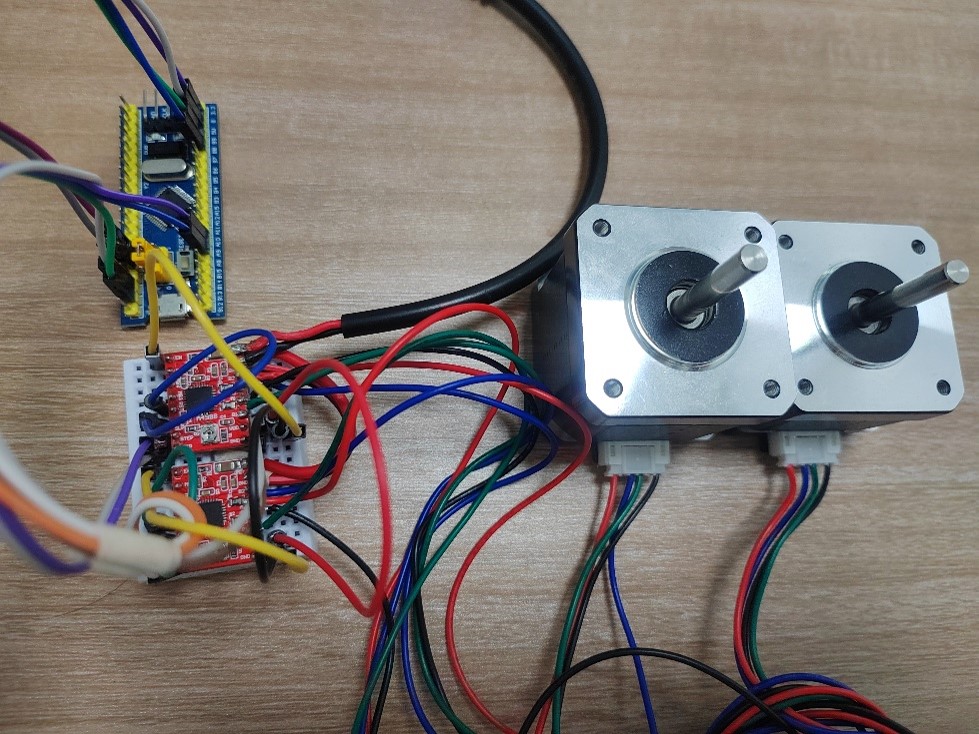
使用硬件型号为:STM32F103C8T6最小系统板、A4988模块、42步进电机(42BYGH39)
1.1 A4988介绍
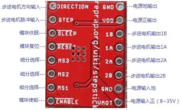
| 引脚 |
功能说明 |
接线 |
| EN |
使能端,低电平有效 |
接GND或单片机IOx1 |
| MS1/2/3 |
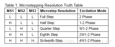
步进模式选择 |
不接或单片机IOx3 |
| SLP |
休眠,高电平有效 |
短接RST |
| STEP |
输入脉冲,一个脉冲转一下 |
单片机IOx1 |
| DIR |
方向位,0/1各代表一方向 |
单片机IOx1 |
| VMOT/GND |
电源接口,直流供电8~35V,最大2A |
12/24V电源 |
| 1A/1B/2A/2B |
步进电机接线 |
步进电机 |
| VDD/GND |
接单片机3.3V和GND |
单片机电源 |
1.2 接线方式
STM32与USB转TTL
| STM32 |
USB转TTL |
| 3.3V/5V |
3.3/5V |
| GND |
GND |
| PA9 |
RXD |
| PA10 |
TXD |
STM32与A4988
| STM32 |
A4988 |
| 3.3V/5V |
VDD |
| GND |
GND |
| PB6 |
STEP(motor.h定义) |
| PB7 |
DIR (motor.h定义) |
|
EN接GND |
|
SLP接RST |
A4988与步进电机
| A4988 |
步进电机 |
| VMOT |
12V电源+ |
| GND |
12V电源- |
| B2 |
B- |
| A2 |
B+ |
| A1 |
A+ |
| B1 |
A- |
需要注意步进电机接线相序
A4988标注的1A、1B、2A、2B,数字代表相、ab代表正负。
步进电机标注的A+、A-、B+、B-,其中AB代表相,±代表正负。
因此接线对应方式应该是:A+和A-对应1A和1B、B+和B-对应2A和2B。比如我的步进电机为黑色A+、绿色A-、红色B+、蓝色B-,那么对应A4988的B2 A2 A1 B1,电机接线顺序就是B- B+ A+ A-(蓝-红-黑-绿)。
如果接错可能会出现电机反转,或只振动不旋转的现象。
1.2 程序设计
本程序为串口控制步进电机,改编自开发板的串口例程,另外编写了步进电机的驱动函数。
GPIO中间的延时表示速度,delay_ms(2)约0.8s每圈,delay_ms(1)约0.4s每圈。
默认情况下(全步进)一个STEP脉冲步进电机转90°。
1
2
3
4
5
6
7
8
9
10
11
12
13
14
15
16
17
18
19
20
21
22
|
#ifndef __MOTOR_H
#define __MOTOR_H
#include "delay.h"
#define Motor_GPIO GPIOF
#define Motor_RCC RCC_APB2Periph_GPIOF
#define Motor1_STEP GPIO_Pin_1
#define Motor1_DIR GPIO_Pin_2
#define Motor2_STEP GPIO_Pin_3
#define Motor2_DIR GPIO_Pin_4
void MOTOR_Init(void);
void motor(unsigned int motor1_dir, unsigned int motor1_step, unsigned int motor2_dir, unsigned int motor2_step);
#endif
|
1
2
3
4
5
6
7
8
9
10
11
12
13
14
15
16
17
18
19
20
21
22
23
24
25
26
27
28
29
30
31
32
33
34
35
36
37
38
39
40
41
42
43
44
45
46
47
48
49
50
51
52
53
54
55
56
57
58
59
60
61
62
63
64
65
66
|
#include "motor.h"
void MOTOR_Init()
{
GPIO_InitTypeDef GPIO_InitStructure;
RCC_APB2PeriphClockCmd(Motor_RCC,ENABLE);
GPIO_InitStructure.GPIO_Pin = Motor1_STEP|Motor1_DIR|Motor2_STEP|Motor2_DIR;
GPIO_InitStructure.GPIO_Mode=GPIO_Mode_Out_PP;
GPIO_InitStructure.GPIO_Speed = GPIO_Speed_50MHz;
GPIO_Init(Motor_GPIO,&GPIO_InitStructure);
GPIO_ResetBits(Motor_GPIO,Motor1_STEP);
GPIO_ResetBits(Motor_GPIO,Motor1_DIR);
GPIO_ResetBits(Motor_GPIO,Motor2_STEP);
GPIO_ResetBits(Motor_GPIO,Motor2_DIR);
}
void motor(unsigned int motor1_dir, unsigned int motor1_step, unsigned int motor2_dir, unsigned int motor2_step)
{
unsigned int i;
switch(motor1_dir)
{
case 0 : GPIO_SetBits(Motor_GPIO,Motor1_DIR); break;
case 1 : GPIO_ResetBits(Motor_GPIO,Motor1_DIR); break;
default : break;
}
switch(motor2_dir)
{
case 0 : GPIO_SetBits(Motor_GPIO,Motor2_DIR); break;
case 1 : GPIO_ResetBits(Motor_GPIO,Motor2_DIR); break;
default : break;
}
for(i = 0;i < motor1_step || i < motor2_step; i++)
{
if(i<motor1_step)
{
GPIO_SetBits(Motor_GPIO,Motor1_STEP);
delay_ms(2);
GPIO_ResetBits(Motor_GPIO,Motor1_STEP);
delay_ms(2);
}
if(i<motor2_step)
{
GPIO_SetBits(Motor_GPIO,Motor2_STEP);
delay_ms(2);
GPIO_ResetBits(Motor_GPIO,Motor2_STEP);
delay_ms(2);
}
}
}
|
1
2
3
4
5
6
7
8
9
10
11
12
13
14
15
16
17
18
19
20
21
22
23
24
25
26
27
28
29
30
31
32
33
34
35
36
37
38
39
40
41
42
43
44
45
46
47
48
49
50
51
52
53
54
55
56
57
58
59
60
61
62
63
64
65
66
67
68
69
70
71
72
73
74
75
76
77
|
#include "delay.h"
#include "sys.h"
#include "usart.h"
#include "mbotLinuxUsart.h"
#include "motor.h"
#define IMAGE_WIDTH 640/2
#define IMAGE_HEIGHT 480/2
short testSend1 =1111;
short testSend2 =2222;
short testSend3 =3333;
unsigned char testSend4 = 0x05;
int testRece1 =400;
int testRece2 =300;
unsigned char testRece3 = 0x00;
int main(void)
{
u8 dir1;
u8 dir2;
u16 step1;
u16 step2;
delay_init();
NVIC_PriorityGroupConfig(NVIC_PriorityGroup_2);
uart_init(115200);
MOTOR_Init();
while(1)
{
usartSendData(testSend1,testSend2,testSend3,testSend4);
if(testRece1>IMAGE_WIDTH)
{
dir1=1;
step1=testRece1-IMAGE_WIDTH;
}
else
{
dir1=0;
step1=IMAGE_WIDTH-testRece1;
}
if(testRece2>IMAGE_HEIGHT)
{
dir2=0;
step2=testRece2-IMAGE_HEIGHT;
}
else
{
dir2=1;
step2=IMAGE_HEIGHT-testRece2;
}
motor(dir1,step1,dir2,step2);
delay_ms(13);
}
}
void USART1_IRQHandler()
{
if(USART_GetITStatus(USART1, USART_IT_RXNE) != RESET)
{
USART_ClearITPendingBit(USART1,USART_IT_RXNE);
usartReceiveOneData(&testRece1,&testRece2,&testRece3);
}
}
|
1.3 实验
STM32从ROS系统获取图像中的目标中心坐标。
receiveData1存放目标x值,receiveData2存放目标y值。
由于ROS系统持续发送坐标值,因此STM32实时接受数据进行控制。A4988采用16细分,每次驱动(50循环)步进5.625°,即每个循环0.1°,可考虑根据目标偏移程度设置每次指令步进大小。例如每差1坐标,每次指令加一个循环0.1°。
