Contents
- Chapter1 How to Create a New Project in VisualStudio2010 Express
- Chapter2 How to Use SB-WinSRC
- Chapter3 Generating a Tetrahedron with OpenGL
- Finding the Normal Vector from 3 Known Points
- Generating a Tetrahedron
- Chapter4 Generating a Point Projection with OpenGL
- Basic Principle for Calculating a Point Projection
- Implementing a Point Projection in Code
- Chapter5 How to Use the VS2010 Debugging Features
- Chapter 6 Importing a Local Model
- How to Create a List
- How to Read a Local Model
- Chapter 7 Matrix Operations
- Translating a Vector with a Matrix
- Rotating a Vector with a Matrix
- Translating and Rotating a Shape
- Rotating the Coordinate System
- Centering a Shape on the Screen and Rotating It About Its Center
- Chapter 8 Building a Small Vehicle
- Assembling a Small Vehicle
- Making the Small Vehicle Move
If you find this article too long, you can read the following separate blog posts: (1) Fundamentals of Digitization Methods (I): Basic Operations and Generating a Tetrahedron (Chapter 1-3) (2) Fundamentals of Digitization Methods (II): Point Projection (Chapter 4-5) (3) Fundamentals of Digitization Methods (III): Importing a Local Model (Chapter 6) (4) Fundamentals of Digitization Methods (IV): Matrix Operations (Chapter 7)
P.S. See commonly used functions here
Latest complete code on Baidu Netdisk: https://pan.baidu.com/s/1cmQwrqrWzPwYdklb7snTkg
Chapter1 How to Create a New Project in VisualStudio2010 Express
1. Create a new win32 Console Application project and choose to create an empty project. A project with precompiled headers will also work, but most people are not accustomed to using them.
 2. Right-click Source in the Solution Explorer on the left, select add-New item, and create a C++ file.
 3. You have now created a simple project with VS2010!
Chapter2 How to Use SB-WinSRC
1. Extract the archive to obtain an SB-WinSRC folder.
2. Open the shinyjet.vcproj file in the SB-WinSrc\examples\projects\microsoft\chapt05\shinyjet folder. If the following dialog box appears, keep clicking Next until you reach the end.
 3. Open shinyjet.cpp and compile it (use Build solution to build the solution).
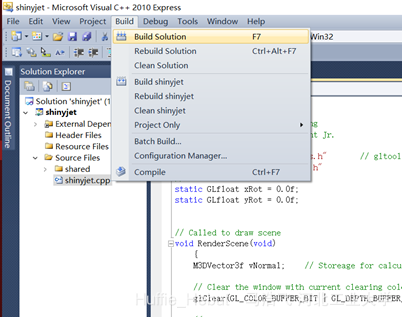 4. The error shown below appears.
 5. Open the \SB-WinSrc\examples\src\shared directory, locate freeglut_static.lib, and copy it into the shinyjet folder opened earlier.
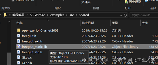
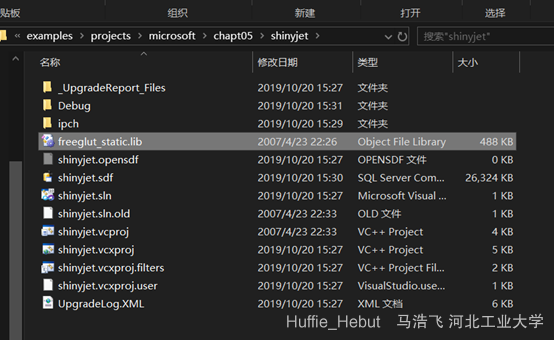 6. Compile again (use Build solution to build the solution), and the error below appears.
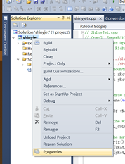
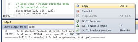 7. In the Solution Explorer on the left, right-click shinyjet to open its properties, and enter LIBC.lib under Linker-Input-Ignore Specific Default Libraries.
 8. Compile again. Success!
Chapter3 Generating a Tetrahedron with OpenGL
Finding the Normal Vector from 3 Known Points
1. The basic idea is to subtract the 3 known points to obtain two vectors, then take the cross product of those two vectors to obtain the normal vector. During implementation, try not to put all the code into one function, because later operations, such as calculating projected points, will also need the function for finding the normal vector. You can then call it directly. 2. The function for finding a vector from 2 known points is very simple:
void getvector(float a[3],float b[3],float vec[3])
{
	for(int i = 0;i < 3;i++)
		vec[i] = a[i] - b[i];
}
3. Call the function above twice to obtain two vectors. The next step is to take their cross product to obtain the normal vector. In the function below, the normal-vector array is defined outside the function beforehand, and the function call assigns its values.
//函数中的法向量n[3]是提前在函数外定义的,通过调用函数给n[3]赋值
void crossproject(float vec1[3],float vec2[3],float n[3])
{
	n[0] = vec1[1]*vec2[2]-vec1[2]*vec2[1];
	n[1] = vec1[2]*vec2[0]-vec1[0]*vec2[2];
	n[2] = vec1[0]*vec2[1]-vec1[1]*vec2[0];
}
4. Wrap the two functions above as follows. Here too, the normal-vector array is defined outside the function beforehand, and the function call assigns its values.
//函数中的法向量n[3]是提前在函数外定义的,通过调用函数给n[3]赋值
void project(float point1[3],float b[3],float c[3],float n[3])
{
	float vec1[3],vec2[3];
	getvector(a,b,vec1);
	getvector(b,c,vec2);
	crossproject(vec1,vec2,n);
}
5. The function for finding a normal vector is now complete. Here is an example of how to use it. After calling project(), the values in the output array are the normal vector.
	double a[3] = {1.0,0.0,0.0};
	double b[3] = {0.0,1.0,0.0};
	double c[3] = {0.0,0.0,0.0};
	double n[3];
	project(a,b,c,n);
	//调用过project()函数之后,n[3]数组内的值即为法向量
Generating a Tetrahedron
1. The basic method for generating a tetrahedron with OpenGL is to provide three points and a normal vector and call an OpenDL library function, which generates a triangular plane enclosed by those three points. Four triangular planes form a tetrahedron.
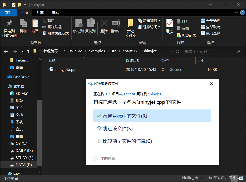
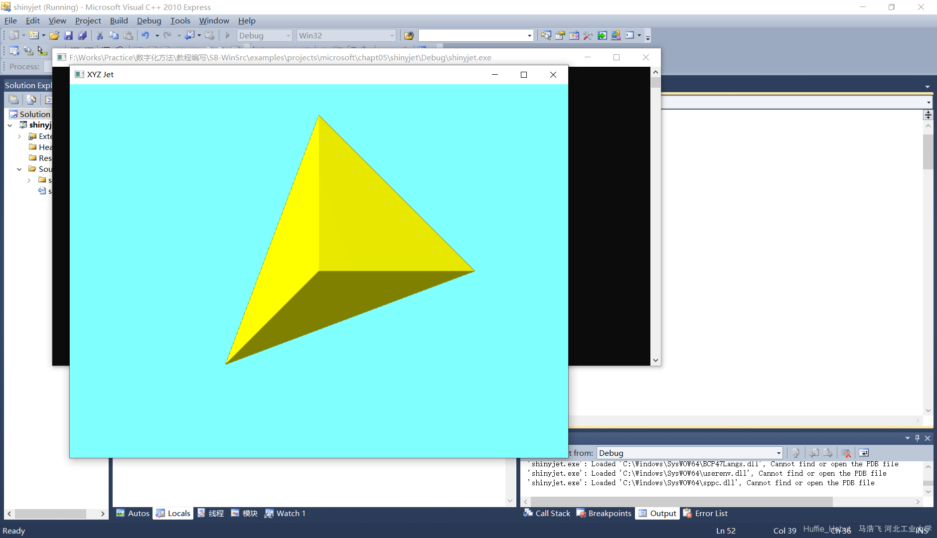
2. Copy the shinyjet.cpp template from class into the corresponding src folder (\SB-WinSrc\examples\src\chapt05\shinyjet). Then return to the corresponding project folder, open the shinyjet.vcxproj project, and click Debug. If it succeeds, a dialog box with a blue-green background should appear.

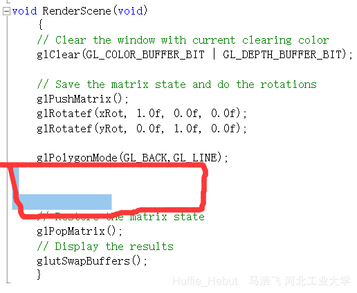
3. At the position shown below in the RenderSenen() function, add the glBegin() and glEnd() functions, and insert the code for drawing triangles between them.
	float rgfPoints4[12] = {-0.6f,-0.6f,-0.6f,
							0.0f,1.0f,0.0f,
							1.0f,0.0f,0.0f,
							0.0f,0.0f,1.0f};
	//这是定义了一个长为12的数组,每3个元素代表一个点坐标,共4个点
	glColor3ub(255,255,0);
	//设置要生成图形的颜色
	glBegin(GL_TRIANGLES);
	//开始生成三角形
	DrawTriangle(rgfPoints4,rgfPoints4+3,rgfPoints4+6);
	DrawTriangle(rgfPoints4,rgfPoints4+9,rgfPoints4+3);
	DrawTriangle(rgfPoints4+3,rgfPoints4+9,rgfPoints4+6);
	DrawTriangle(rgfPoints4,rgfPoints4+6,rgfPoints4+9);
	//↑函数功能:给定3个点生成一个三角形,调用4次生成4个三角形组成四面体
    glEnd();
    //结束
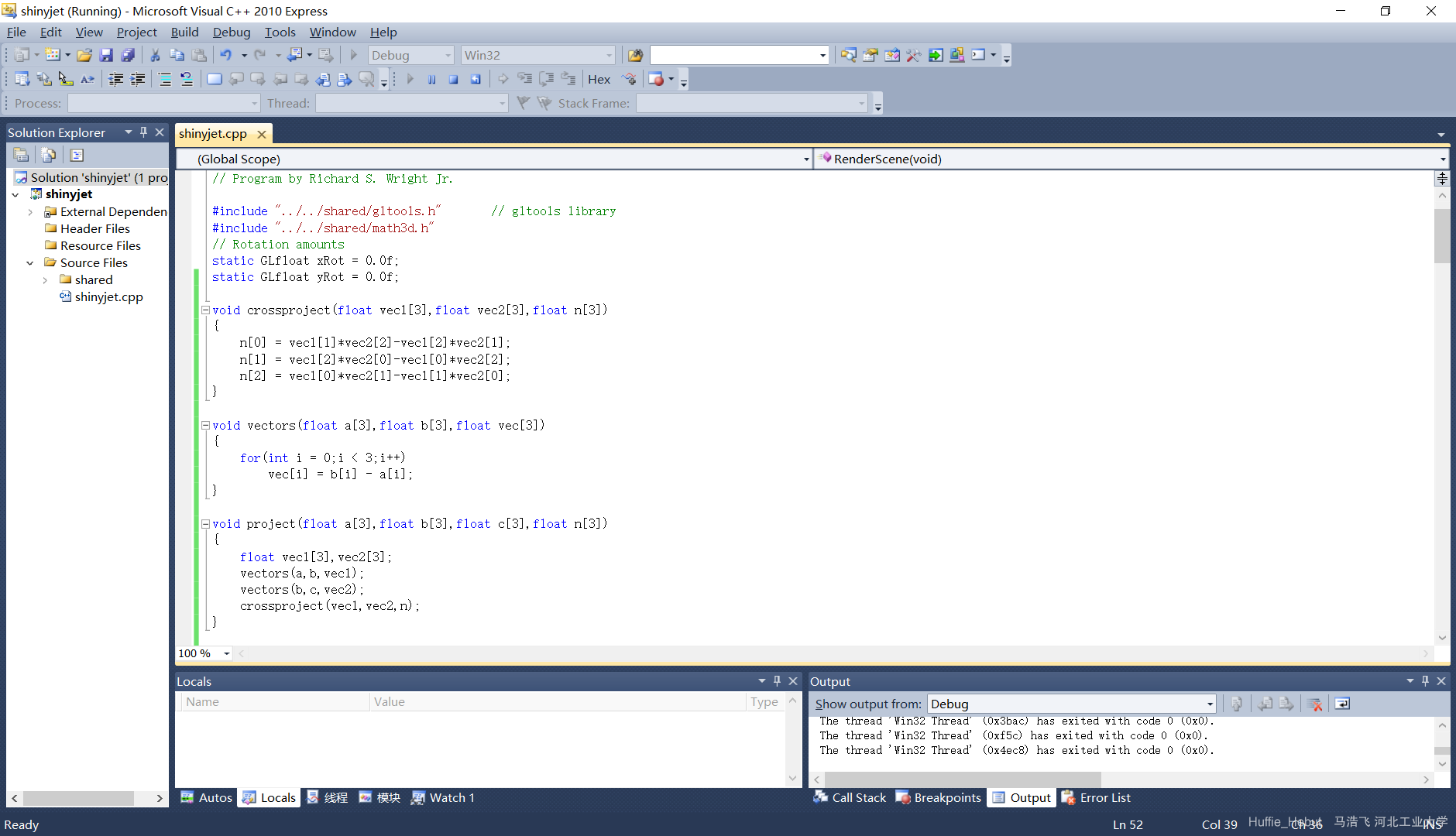
4. Here, glColor3ub, glBegin, and glEnd are all OpenGL library functions. We do not need to define them and can call them directly. What we need to write is the DrawTriangle function. Next, we will define DrawTriangle(). As mentioned earlier, a plane requires 3 points and a normal vector, so copy the function that generates a normal vector from the first section to the beginning of this file so it can be called.
 5. The function for drawing a triangle is shown below. It defines an array for the normal vector, calculates the normal vector n from the three points a, b, and c, and then uses library functions to generate a plane from n and the three points.
void DrawTriangle(float a[3],float b[3],float c[3])
{
	float n[3];	//定义一个数组用来存放法向量
	project(a,b,c,n);	//调用生成法向量的函数由a,b,c三点生成法向量n
	glNormal3fv(n);
	glVertex3fv(a);
	glVertex3fv(b);
	glVertex3fv(c);		//此四行为利用用库函数,由法向量n和三个点abc生成一个平面
}
5. After completing the steps above, debug the program to obtain a tetrahedron.
Chapter4 Generating a Point Projection with OpenGL
Basic Principle for Calculating a Point Projection

Implementing a Point Projection in Code
1. To implement a point projection, we need to know the coordinates of the projected point. As the previous section shows, we need to calculate the P0P1 vector (by directly calling the function for finding a vector from the previous lesson), the en vector (which requires a normalization function), and the vector dot product. 2. Normalization means dividing every coordinate of a vector by its magnitude. The function is shown below. It calculates the vector’s magnitude, then turns the input array into a unit normal vector.
void Normalize(float n[3])
{
	float length;
	length = sqrt(n[0]*n[0]+n[1]*n[1]+n[2]*n[2]);
	//求向量的模
	for(int i = 0;i < 3;i++)
		n[i] /= length;
	//函数执行过后n[3]即变成单位法向量
}
3. Calculate the vector dot product and find the coordinates of point N. The vector between a point in the plane and a point outside it is the vector shown in the diagram. The dot product gives the distance from the point to the plane, and subtracting the unit normal scaled by this distance gives the coordinates of point N.
void ProjectPointtoPoint(float point[3],float a[3],float n[3], float ProjectPoint[3])
{
	float vector_a_p[3];
	float distance;
	for(int i = 0;i < 3;i++)
		vector_a_p[i] = point[i] - a[i];
	//求面内一点与面外一点的向量,即P0P1
	distance = vector_a_p[0]*n[0]+vector_a_p[1]*n[1]+vector_a_p[2]*n[2];
	//做点乘运算求点到平面距离,即图中|P0N|
	for(int j = 0;j < 3;j++)
		ProjectPoint[j] = point[j] - n[j]*distance;
	//N点坐标=P0坐标 - en * |P0N|
}
4. After the steps above, we have the projected point’s coordinates and can call a library function to display it. The following function displays one point. It finds the normal vector of plane abc, normalizes it, defines an array for the projected point’s coordinates, obtains those coordinates, and displays the projected point.
void DrawPoint(float a[3],float b[3],float c[3],float point[3])
{
	float n[3];
	project(a,b,c,n);
	//求abc平面法向量
	Normalize(n);
	//单位化法向量
	float ProjectPoint[3];
	//定义一个数组用来存放投影点坐标
	ProjectPointtoPoint(point,a,n,ProjectPoint);
	//获得投影点坐标
	glVertex3fv(ProjectPoint);
	//显示投影点
}
5. As with the triangles, after the glEnd() that draws the triangles in RenderSenen(), add glBegin() and glEnd() again, and insert the code for displaying points between them.
	float point[3] = {0.0f,0.0f,0.0f};
	//定义要投影的点
	glColor3ub(0,0,0);
	//显示的点的颜色
	glPointSize(6.0f);
	//显示的点的大小
	glBegin(GL_POINTS);
	//开始生成点
	DrawPoint(rgfPoints4,rgfPoints4+3,rgfPoints4+6,point);
	//根据第一个面3个点,画第一个投影点
	DrawPoint(rgfPoints4,rgfPoints4+9,rgfPoints4+3,point);
	DrawPoint(rgfPoints4+3,rgfPoints4+9,rgfPoints4+6,point);
	DrawPoint(rgfPoints4,rgfPoints4+6,rgfPoints4+9,point);
	glEnd();
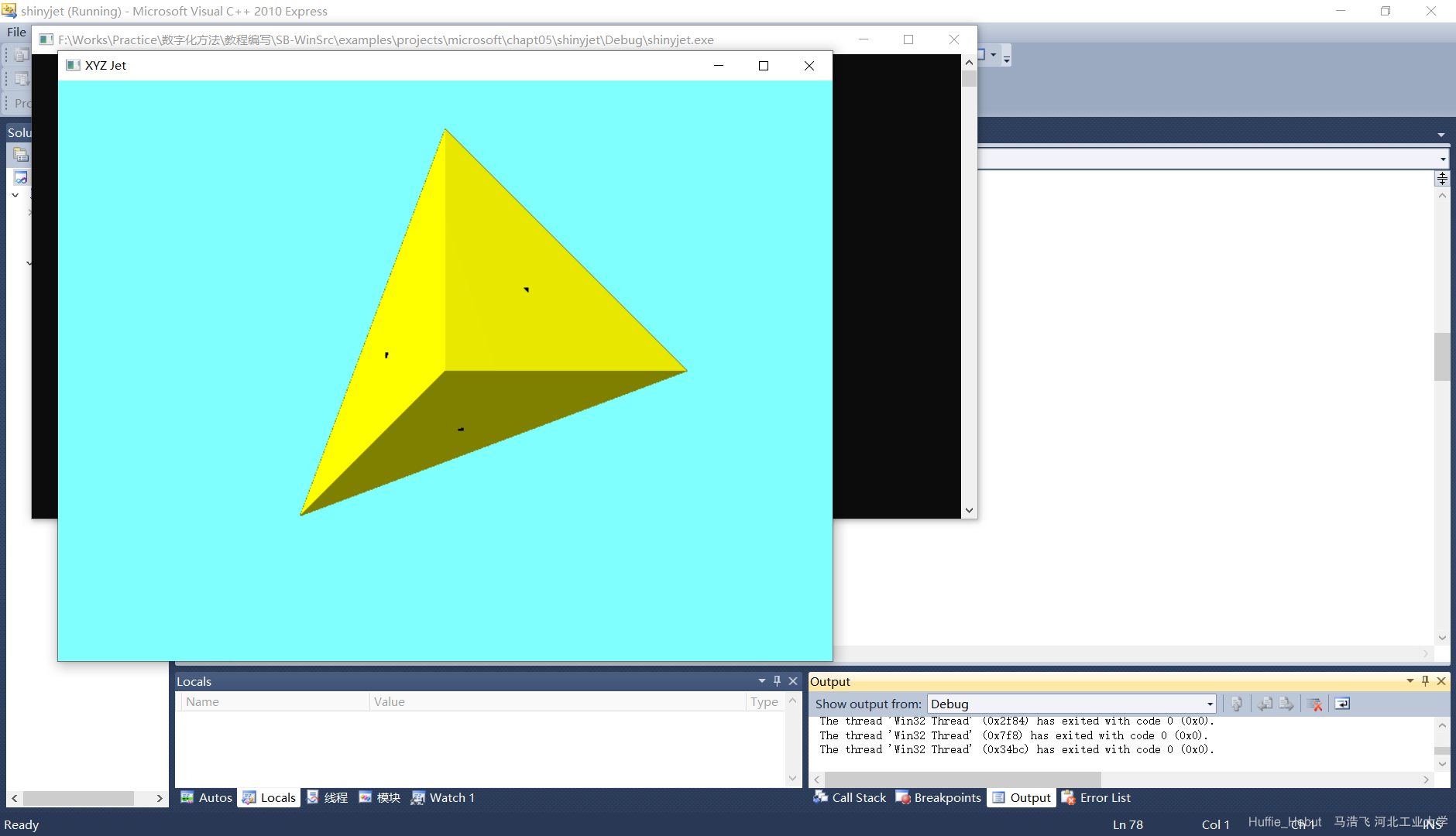
6. Debugging succeeds, and the result is shown below.
Chapter5 How to Use the VS2010 Debugging Features
Suppose I finish writing and debugging the program but find that the point is not displayed. I can debug it step by step to locate the error.
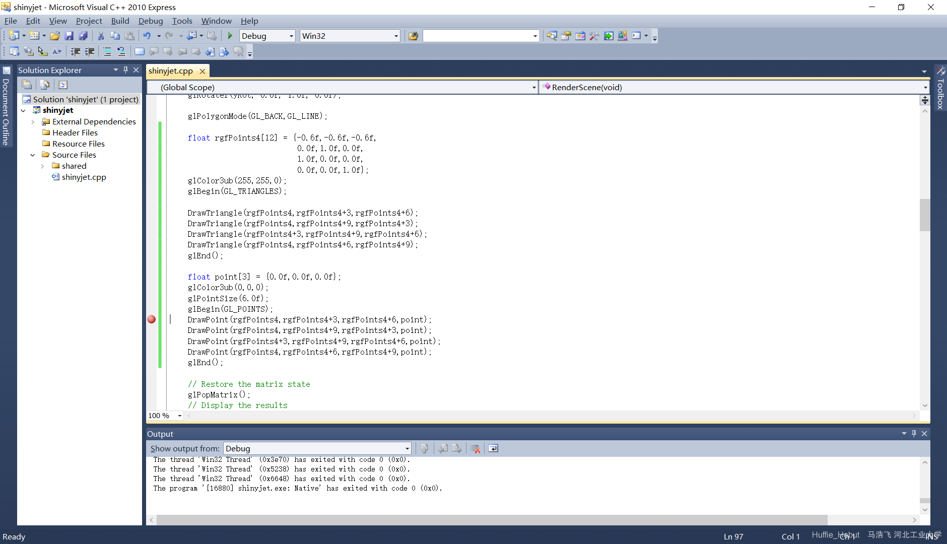
1. Set a breakpoint where you think the problem may be.
 2. Click Debug. Of the two buttons in the red box below, the button on the left steps through one statement each time you click it. If it encounters a function, it enters the function and executes the first statement in its body. The button on the right also executes one statement per click, but when it encounters a function, it executes the whole function directly, treating the function as one statement.
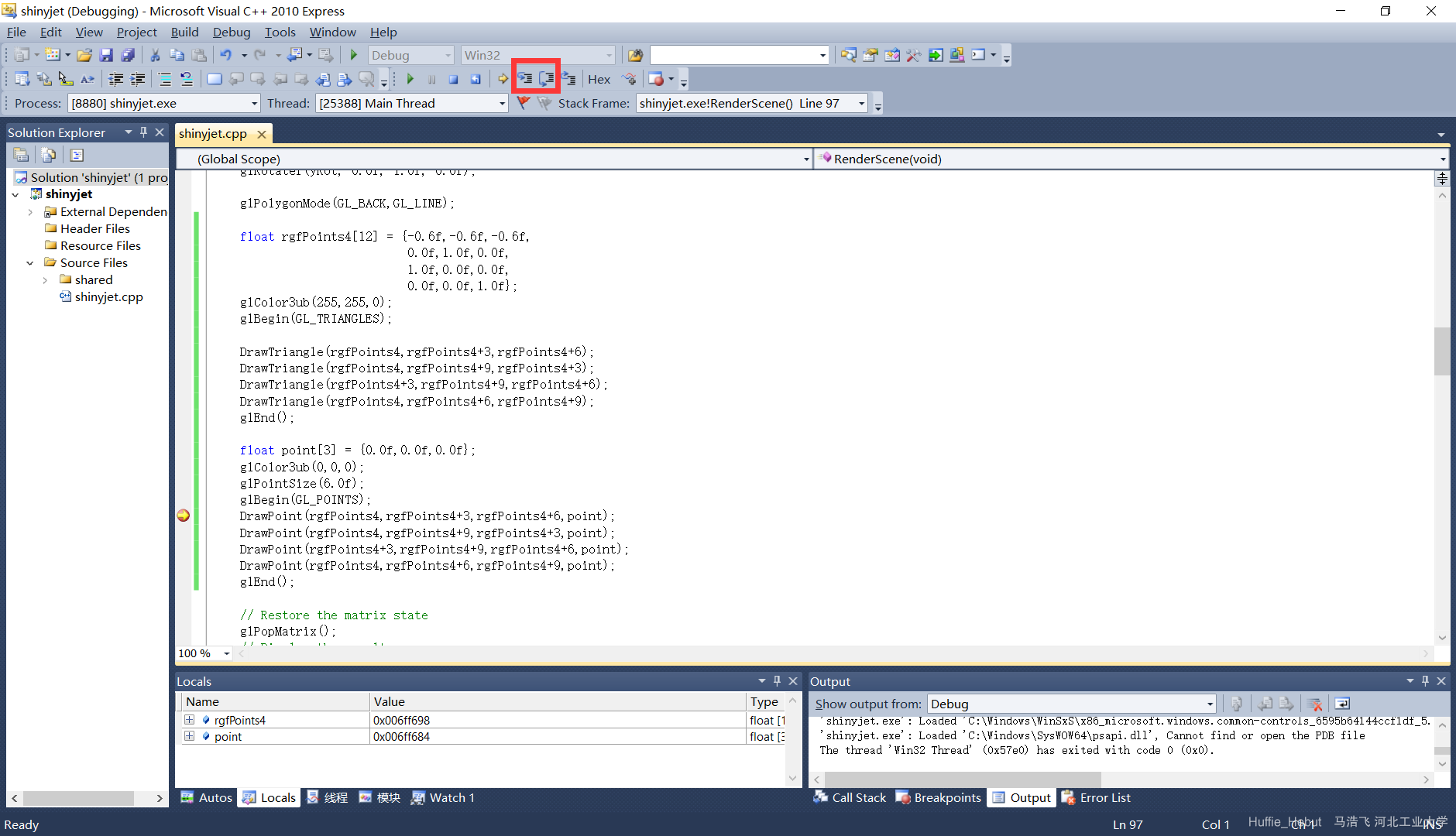 3. Here, select the button on the left to enter the function. The yellow arrow indicates the statement currently being executed.
 4. Press the second button to finish executing this function (but do not exit it; otherwise, the memory for its local variables will be released and you will be unable to inspect their values).
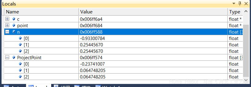
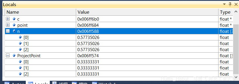
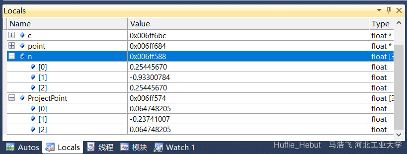
 5. You can now see variables in the Watch window below. Click + to see their values. The expanded values in the figure are the normal vector and projected point coordinates for the first face.
 The normal vector and projected point coordinates for the second face:
 The third face:
 The fourth:
Chapter 6 Importing a Local Model
Generating graphics takes time. You may not notice it with a simple model, but generating a highly complex model takes quite a long time, which is unacceptable. Therefore, it is essential to save a model as a local file and load it directly when needed. This section mainly explains how to create a list and load a list.
How to Create a List
The basic principle of a list is to replace the code written earlier—from glPolygonMode and glBegin through glEnd—with one line, glCallList(DrawList). DrawList stores the code that generated the tetrahedron earlier. glCallList is equivalent to loading the original tetrahedron code. How do we turn the original tetrahedron code into a list that glCallList can read? The process is very simple; just follow these steps: 1. At the beginning of the entire file, define a global variable of type GLuint (because this variable is used in different functions, it must be global).
GLuint DrawList;2. In the RenderScene function (where glbegin and glEnd were written earlier), replace all triangle-related code with the glCallList function.
3. At the end of the SetupRC function, create a new list using the following framework.
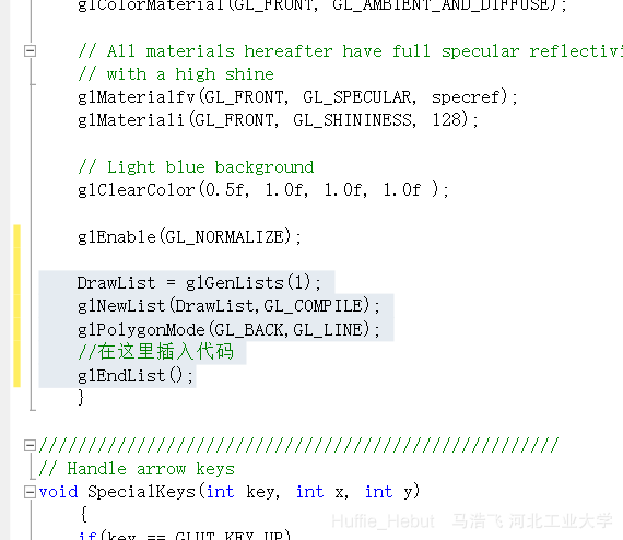 4. After writing the framework, insert the tetrahedron-drawing code at the comment shown in the figure. The result after insertion is shown below.
 5. At this point, a list containing the tetrahedron has been created. Click Debug to run it, and you will see the same tetrahedron as before.
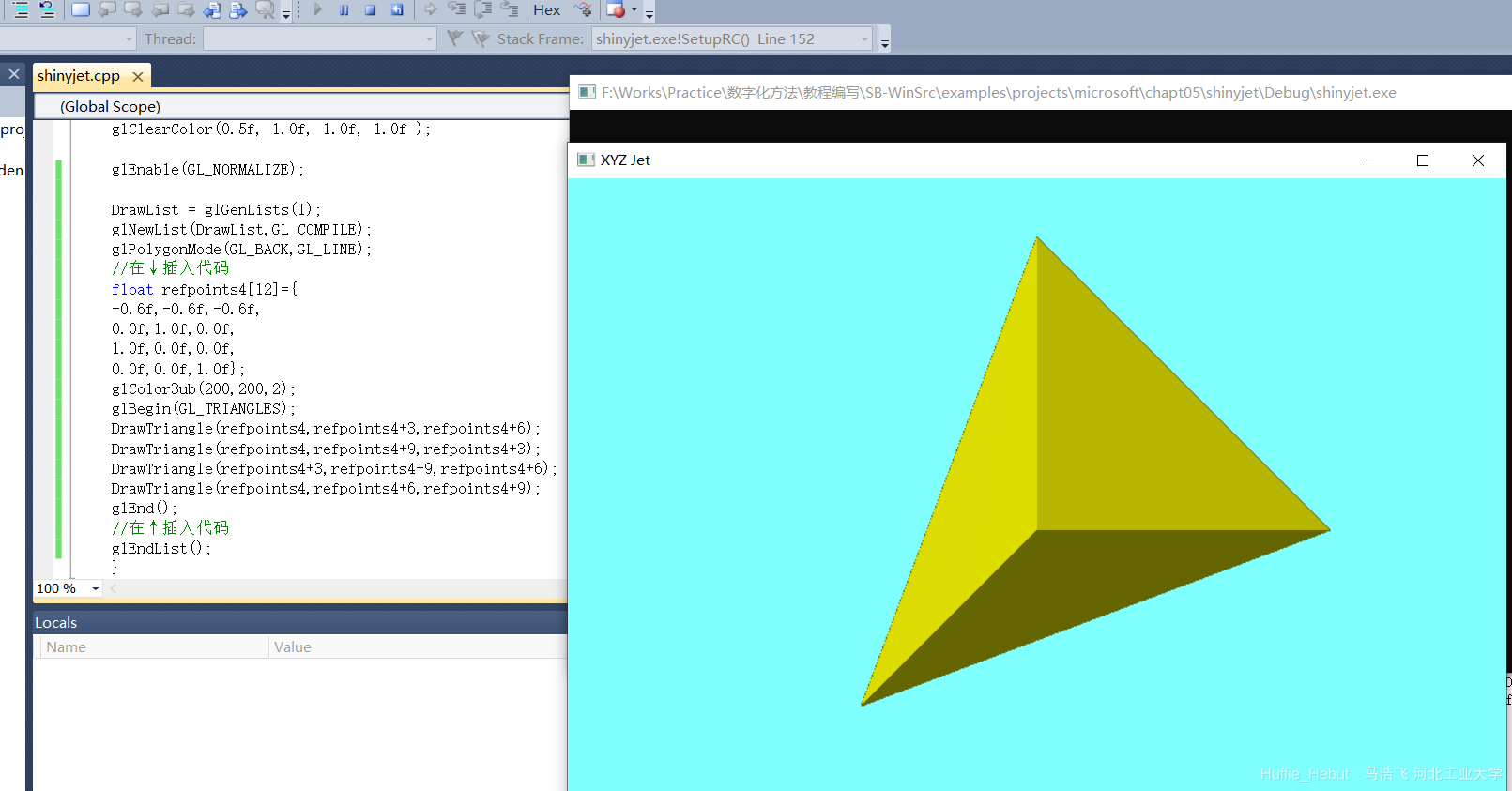
How to Read a Local Model
What should we do when we need to read a model from a local file?
1. Since we need to read the model from a file, we must first open the file. Insert the following three lines before the code that creates the list.
 (Note that the parentheses of if stream contain the file path. Every \ in it must be written as \, because in a C-language string, \ indicates an escape, and \\ represents a single .)
(Note that to use ifstream, you must first insert the following two lines at the beginning to include the header and set up the environment.)
(Note that the parentheses of if stream contain the file path. Every \ in it must be written as \, because in a C-language string, \ indicates an escape, and \\ represents a single .)
(Note that to use ifstream, you must first insert the following two lines at the beginning to include the header and set up the environment.)
#include<fstream>
using namespace std;
2. Define several arrays to store the data that will be read shortly.
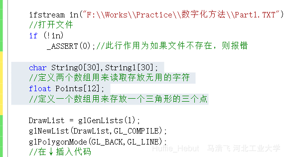 3. Then replace the previous tetrahedron-drawing code with code that reads the file. The revised framework is shown below. Each read by in retrieves a sequence of characters and stops at a space or newline. in >> String0 means storing the characters that were read in String0.
	DrawList = glGenLists(1);
	glNewList(DrawList,GL_COMPILE);
	glPolygonMode(GL_BACK,GL_LINE);
	//在↓插入代码
	in >> String0 >> String0;//这就表示将两个字符串先后存入到String0中
	//因为如下图在读取到有用数据之前有两个没用的单词,需要读取两次
	while(strcmp(String0,"end"))//读到的字符串为end则退出循环
	{
		in >> Points[0] >> Points[1] >> Points[2];
//因为刚才已经读掉了前两个没用的字符串,因此直接读取三个坐标到Points里
		in >> String0 >> Points[3] >> Points[4] >> Points[5];
//如下图读完第一组坐标后会遇到 vertex这个单词,需要读到垃圾桶(String0)里再读坐标
		in >> String0 >> Points[6] >> Points[7] >> Points[8];
//同上
		glColor3ub(200,200,2);
		glBegin(GL_TRIANGLES);
		DrawTriangle(Points,Points+3,Points+6);
//这三行时画一个三角形,根据刚才读到的三个点
		in >> String0;
	}
	//在↑插入代码
	glEndList();
(Because the strcmp function is used, the header #include<string.h> must be included.)

 One thing to note is that computer graphics, whether planar or curved, are composed of countless triangles. When there are an enormous number of triangles, the shape simply looks like a curved surface. The same is true in the Part1.TXT file: each time three points are read, one triangle is drawn, and many triangles together form a solid shape.
4. This completes the process of importing a solid model from a file. Click Debug, and you will see a cube.
6. How do we read a given STL file? First, right-click Part2.STL and open it with Notepad. Its contents are shown below.
One thing to note is that computer graphics, whether planar or curved, are composed of countless triangles. When there are an enormous number of triangles, the shape simply looks like a curved surface. The same is true in the Part1.TXT file: each time three points are read, one triangle is drawn, and many triangles together form a solid shape.
4. This completes the process of importing a solid model from a file. Click Debug, and you will see a cube.
6. How do we read a given STL file? First, right-click Part2.STL and open it with Notepad. Its contents are shown below.
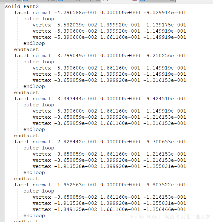 This looks similar to the previous file, except that it provides an additional normal vector and contains more useless strings. You can ignore the provided normal vector, read only the three coordinates, and calculate the normal vector yourself, or you can read the normal vector. In the latter case, the DrawTriangle function no longer needs to calculate the normal vector; the same four lines of code are sufficient. As before, each in >> String0 operation consumes one useless string. You can write the code yourself to read all the points from the STL file.
Note that at the end of each loop, you must make sure that String contains the word facet or the final endsolid so that the loop can exit normally.
This looks similar to the previous file, except that it provides an additional normal vector and contains more useless strings. You can ignore the provided normal vector, read only the three coordinates, and calculate the normal vector yourself, or you can read the normal vector. In the latter case, the DrawTriangle function no longer needs to calculate the normal vector; the same four lines of code are sufficient. As before, each in >> String0 operation consumes one useless string. You can write the code yourself to read all the points from the STL file.
Note that at the end of each loop, you must make sure that String contains the word facet or the final endsolid so that the loop can exit normally.
void DrawTriangle(float a[3],float b[3],float c[3],float n[3])
{
	//float n[3];
	//project(a,b,c,n);
	glNormal3fv(n);
	glVertex3fv(a);
	glVertex3fv(b);
	glVertex3fv(c);
}
P.S. If the program reports an error, how should you debug it? First, set a breakpoint before the first statement in the while loop, as shown below.
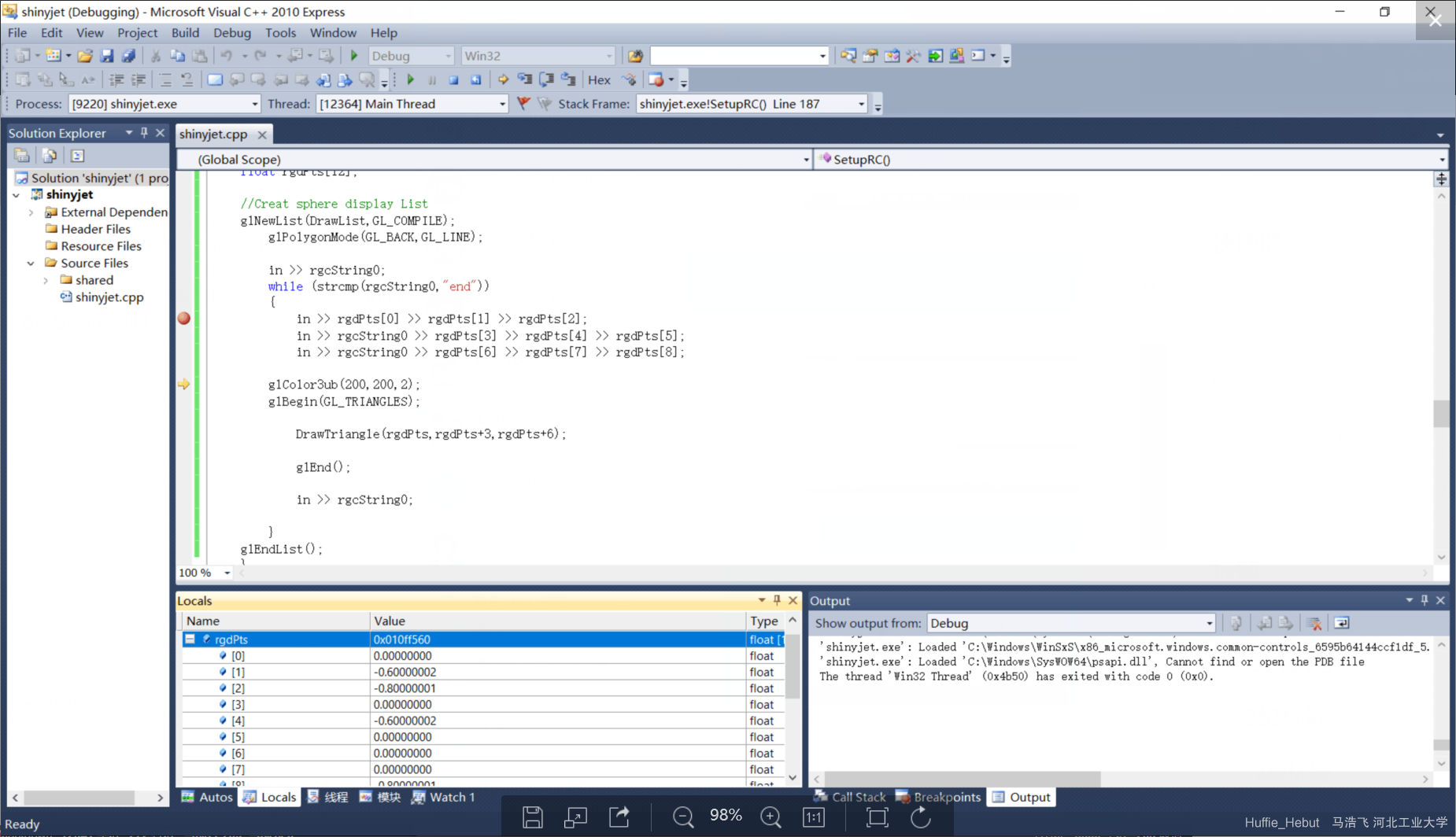 Then click the second step button.
 Each loop reads 9 points. Check whether the point values you read correspond one-to-one with the coordinate values in the file: 012 correspond to the 3 points on the first line, 345 correspond to the three points on the second line, and 678 correspond to the third line.

Chapter 7 Matrix Operations
Translating a Vector with a Matrix
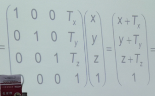
1. Basic principle: As shown in the figure, take the coordinates x,y,z of any given point (a column vector). By setting up a matrix and using matrix multiplication, you can translate the three coordinates.
Note: The matrix used in this process is the identity matrix with the offsets Tx, Ty, and Tz added to its final column. As shown below, you can verify this by trying the matrix multiplication yourself.
2. After understanding how to translate a column vector, we can write a program to perform vector translation. Open the program that generates a helix. Notice that the helix consists of many points. The for loop below generates one point at a time. We only need to translate each point’s coordinate vector to translate the entire helix.
 3. Now we can start writing the program. First, clarify its execution process:
1. Obtain the coordinates of a point and store them in the P0 array. 2. Set up a Translation matrix for translating the coordinates. 3. Multiply the two matrices above and store the result in the P1 array; this gives the translated point coordinates.
4. First, obtain the coordinates of a point and store them in the P0 array. This step is very simple (note: except for function definitions, all remaining code is inside the for loop): float P0[3] = {x,y,z};
5. Second, set up a Translation matrix for translating the coordinates. We need a matrix like the one below.
 How do we do this? First initialize an identity matrix, then assign the required offsets to its final column. (My code is very simple and brute-force, though you can of course write a separate function to initialize an identity matrix.)
Note: In OpenGL, matrices are stored by column. In other words, the first four elements I[1], I[2], I[3], and I[4] of the I[16] I defined actually form the matrix’s first column, while the final I[12], I[13], I[14], and I[15] form its final column, not the final row as understood in last semester’s C programming course.
How do we do this? First initialize an identity matrix, then assign the required offsets to its final column. (My code is very simple and brute-force, though you can of course write a separate function to initialize an identity matrix.)
Note: In OpenGL, matrices are stored by column. In other words, the first four elements I[1], I[2], I[3], and I[4] of the I[16] I defined actually form the matrix’s first column, while the final I[12], I[13], I[14], and I[15] form its final column, not the final row as understood in last semester’s C programming course.
void Translate(float fx,float fy,float fz,float Translation[16])
{
	float I[16] = {1.0f,0.0f,0.0f,0.0f,0.0f,1.0f,0.0f,0.0f,0.0f,0.0f,1.0f,0.0f,0.0f,0.0f,0.0f,1.0f};//定义一个四阶单位阵
	I[12] = fx;//将第四列第一行的元素赋fx
	I[13] = fy;//第四列第二行赋fy
	I[14] = fz;//第四列第三行赋fz
	for(int i = 0;i < 16;i++)
		Translation[i] = I[i];//将I数组的值循环赋给Translation数组
}
After this operation, we obtain the array shown in the preceding image.
6. Third, multiply the two matrices above and store the result in the P1 array; this gives the translated point coordinates. So all we need to do is define a P1 array, float P1[3];, which is very simple, and then write a matrix multiplication operation that calculates Translation*P0 and stores the result in P1.
The implementation is shown below. Note that translation is a 4*4 matrix, P0 is a 3*1 matrix, and P1 is a 4*1 matrix.
(We need a fourth-order matrix because matrix-based translation requires one additional row and column, while we actually use only the first 3 elements of P0 and P1.)
Therefore, we assume that P0’s “fourth” element is 1; that is, the final term in the code below is 1*translation[i+12].
void ApplyMatrix(float *P0,float *translation,float *P1)
{
	for(int i = 0;i < 3;++i)
		P1[i] = P0[0]*translation[i]+P0[1]*translation[i+4]+P0[2]*translation[i+8]+translation[i+12];
}
7. With the Translate function for setting up the transformation matrix and the ApplyMatrix function for matrix multiplication, we can translate points.
for(angle = 0.0f; angle <= (2.0f*GL_PI)*3.0f; angle += 0.1f)
		{
		x = 50.0f*sin(angle);
		y = 50.0f*cos(angle);

		// Specify the point and move the Z value up a little
		glVertex3f(x, y, z);
		float P0[3] = {x,y,z};	//定义P0存放平移之前的点
		float P1[3];			//定义P1存放平移之后的点
		float Translation[16];	//存放一个4*4的操作矩阵

		Translate(0.0f,30.0f,0.0f,Translation);
		//设置操作矩阵为我们想要的格式(单位阵->最后一列赋值)
		ApplyMatrix(P0,Translation,P1);
		//操作矩阵和P0点相乘,结果放在P1内
		glVertex3f(P1[0], P1[1], P1[2]);
		//显示平移之后的点
		z += 0.5f;
		}
The above steps translate the helix.
Rotating a Vector with a Matrix
1. How to rotate a vector
First, consider the rotation of two-dimensional coordinates. Suppose a vector a has coordinates (x,y), length r, and an angle α with the positive x-axis:
xa = r cos α,
ya = r sin α.
If the vector is rotated through an angle φ, the coordinates of the new vector b are
xb = r cos(α + φ) = r cos α cos φ - r sin α sin φ,
yb = r sin(α + φ) = r sin α cos φ + r cos α sin φ.
 Since xa = r cos α,ya = r sin α. it is easy to see that
xb = xa cos φ - ya sin φ,
yb = ya cos φ + xa sin φ.
The right-hand side of these equations can also be written as the product of two matrices.
Since xa = r cos α,ya = r sin α. it is easy to see that
xb = xa cos φ - ya sin φ,
yb = ya cos φ + xa sin φ.
The right-hand side of these equations can also be written as the product of two matrices.
 This shows that the second-order square matrix composed of sin and cos in the equation can rotate the vector (xa ya,) into (xb,yb,). For now, call it the second-order rotation matrix.
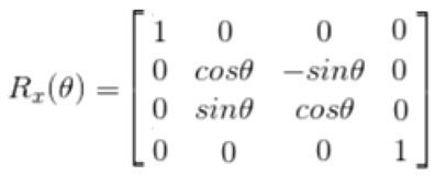
Extending this derivation to third order gives the following three third-order rotation matrices (for rotation about the x, y, and z axes, respectively). Substitute values to verify them yourself.
This shows that the second-order square matrix composed of sin and cos in the equation can rotate the vector (xa ya,) into (xb,yb,). For now, call it the second-order rotation matrix.
Extending this derivation to third order gives the following three third-order rotation matrices (for rotation about the x, y, and z axes, respectively). Substitute values to verify them yourself.
 To keep this consistent with the previous translation operation, we also extend this third-order rotation matrix to fourth order, as shown below.
 2. How do we write a function to rotate a vector?
From the preceding derivation, we know that left-multiplying a column vector by a rotation matrix rotates the vector.
Now we can write the function. Using rotation about the x-axis as an example, first look at the “main function,” which is the loop that generates the helix.
2. How do we write a function to rotate a vector?
From the preceding derivation, we know that left-multiplying a column vector by a rotation matrix rotates the vector.
Now we can write the function. Using rotation about the x-axis as an example, first look at the “main function,” which is the loop that generates the helix.
for(angle = 0.0f; angle <= (2.0f*GL_PI)*3.0f; angle += 0.1f)
		{
		x = 50.0f*sin(angle);
		y = 50.0f*cos(angle);

		// Specify the point and move the Z value up a little
		glVertex3f(x, y, z);
		float P0[3] = {x,y,z};
		float P1[3];

		float Rotation[16] = {0};
//定义一个数组(用于存放旋转操作矩阵)
//这里也可生成一个单位阵,那样就不用初始化为0了
		Rotate_x(-90,Rotation);
//给定一个角度(-90°),生成旋转操作矩阵
		ApplyMatrix(P0,multi,P1);
//用旋转操作矩阵左乘P0,得到的结果P1即为旋转完成的向量坐标
		glVertex3f(P1[0], P1[1], P1[2]);
//显示旋转后的坐标对应的点
		z += 0.5f;
		}
Therefore, what we need to do is write a function that generates a rotation matrix from its parameter (the angle). Note that the math.h header provides sin and cos functions, which can be called directly as sin(angle), where angle is a value in radians. The code is shown below.
(Note that PI used in the function is defined by the macro #define PI 3.14159 at the beginning.)
void Rotate_x(float angle,float *rotation)
{
	angle = angle/180.0*PI;
//将角度值转换为弧度值
	rotation[5] = cos(angle);
	rotation[6] = sin(angle);
	rotation[9] = -sin(angle);
	rotation[10] = cos(angle);
	rotation[0] = 1;
	rotation[15] = 1;
//配置各个位置的数值,注意矩阵下标是竖着数的,第一行位置为0、4、8、12
}
This gives us the rotation matrix, which the “main function” can call to rotate the vector.
Translating and Rotating a Shape
A very simple approach is to call the translation and rotation functions in sequence, as shown below.
for(angle = 0.0f; angle <= (2.0f*GL_PI)*3.0f; angle += 0.1f)
		{
		x = 50.0f*sin(angle);
		y = 50.0f*cos(angle);

		// Specify the point and move the Z value up a little
		glVertex3f(x, y, z);
		float P0[3] = {x,y,z};
		float P1[3];
		float P2[3];

		float Translation[16];
		Translate(0.0f,60.0f,0.0f,Translation);
ApplyMatrix(P0,Translation,P1);
//进行平移操作,P0平移后为P1

		float Rotation[16] = {0};
		Rotate_x(-90,Rotation);
ApplyMatrix(P1,Rotation,P2);
//进行旋转操作,P1旋转后为P2

		glVertex3f(P2[0], P2[1], P2[2]);
//最后输出P2的点即可
		z += 0.5f;
		}
However, this is clearly not what we want. We want to complete the translation in one step, without an intermediate P1. To do that, we need to multiply the translation matrix and rotation matrix to obtain another fourth-order matrix, then left-multiply the column vector xy by this new fourth-order matrix to translate and rotate the column vector.
How should we understand this?
We know that the translation matrix and rotation matrix are both invertible matrices (det Rx ≠ 0,det T ≠ 0).
 Both matrices can therefore be written as products of many elementary matrices:
Rx = R1*R2*R3*……Rn * I
T = R1’*R2’*R3’……Rn’ * I
(Here, R1,R1’……Rn,Rn’ are all elementary matrices. Remember elementary matrices? We just learned about them in linear algebra. An elementary matrix performs only one elementary transformation; left-multiplying a matrix by an elementary matrix performs a row operation on it.)
We know that the translation operation is
Both matrices can therefore be written as products of many elementary matrices:
Rx = R1*R2*R3*……Rn * I
T = R1’*R2’*R3’……Rn’ * I
(Here, R1,R1’……Rn,Rn’ are all elementary matrices. Remember elementary matrices? We just learned about them in linear algebra. An elementary matrix performs only one elementary transformation; left-multiplying a matrix by an elementary matrix performs a row operation on it.)
We know that the translation operation is
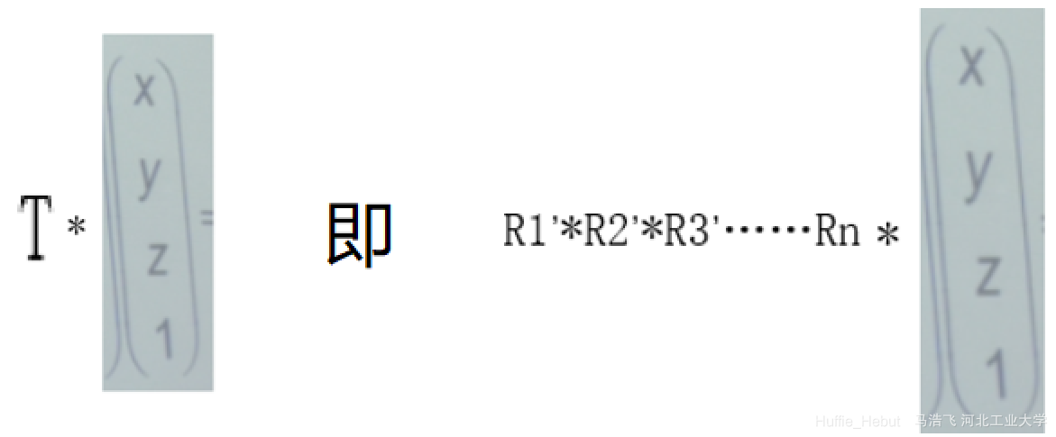 Likewise, the rotation operation can also be written as
 Translating first and then rotating the translated matrix can be written in the following form.
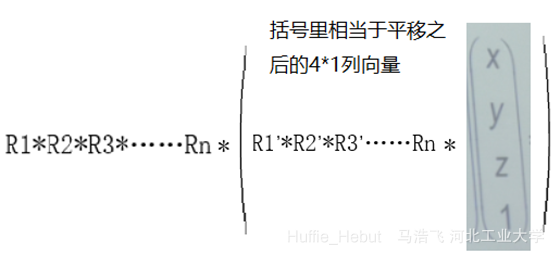 Since Rx = R1R2R3*……Rn,T = R1’R2’R3’……Rn’, RxTcolumn vector represents translating and rotating the column vector.
We now need to write a fourth-order matrix multiplication function to obtain the result of Rx*T. Left-multiplying the column vector by this result performs translation and rotation in one step.
The code for fourth-order matrix multiplication is shown below.
Since Rx = R1R2R3*……Rn,T = R1’R2’R3’……Rn’, RxTcolumn vector represents translating and rotating the column vector.
We now need to write a fourth-order matrix multiplication function to obtain the result of Rx*T. Left-multiplying the column vector by this result performs translation and rotation in one step.
The code for fourth-order matrix multiplication is shown below.
void mul(float *rotation,float *translation,float *tran)
{
	for(int i = 0;i < 4;i++)
		for(int j = 0;j < 4;j++)
			for(int k = 0;k < 4;k++)
				tran[4*i+j] += rotation[4*k+j]*translation[4*i+k];
}
Note that a variable with 16 elements represents one matrix here, which makes the indices rather troublesome. You can write them out on paper. This is not the only way to write the code. You can also split it into four separate loops, or directly assign every element, for 16 assignments in total. Then call it in the “main function” according to the logic above.
for(angle = 0.0f; angle <= (2.0f*GL_PI)*3.0f; angle += 0.1f)
		{
		x = 50.0f*sin(angle);
		y = 50.0f*cos(angle);

		// Specify the point and move the Z value up a little
		glVertex3f(x, y, z);
		float P0[3] = {x,y,z};
		float P1[3];

		float Translation[16];
		Translate(0.0f,60.0f,0.0f,Translation);
//获得平移操作矩阵
		float Rotation[16] = {0};
		Rotate_x(-90,Rotation);
//获得旋转操作矩阵

		float multi[16] = {0};
		mul(Rotation,Translation,multi);
//两矩阵相乘获得平移+旋转操作矩阵
		ApplyMatrix(P0,multi,P1);
//用平移+旋转操作矩阵左乘P0即可得到被平移且旋转之后的矩阵P1
		glVertex3f(P1[0], P1[1], P1[2]);
		z += 0.5f;
		}
The above procedure translates and rotates a vector using matrices.
Rotating the Coordinate System
1. Objective:
Given a vector such as (1,1,1), rotate the original coordinate system into a coordinate system whose Z-axis is this vector.
2. Basic concept:
As shown in the figure, each column in the third-order square matrix on the left contains the three unit vectors of the new coordinate axes. Left-multiplying a point in the original coordinate system by this third-order square matrix rotates the point’s coordinates to the corresponding coordinates in the new coordinate system.
Therefore, we only need to generate the coordinate-system rotation matrix shown on the left.
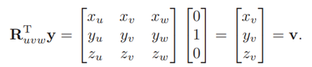 3. How to Generate the Ruvw Matrix
Method One:
(1) First normalize the known vector z.
(2) Then change one coordinate of the known vector z to 1, producing two vectors in the same plane.
(3) Take the cross product of the two vectors. The result is vector y, which is perpendicular to the known vector z.
(4) Then take the cross product of the known vector z and the newly obtained vector y to obtain vector x, which is perpendicular to both.
(5) Arrange the three resulting coordinate-axis vectors in the following form (u is the new x-axis, v is the new y-axis, and w is the new z-axis).
3. How to Generate the Ruvw Matrix
Method One:
(1) First normalize the known vector z.
(2) Then change one coordinate of the known vector z to 1, producing two vectors in the same plane.
(3) Take the cross product of the two vectors. The result is vector y, which is perpendicular to the known vector z.
(4) Then take the cross product of the known vector z and the newly obtained vector y to obtain vector x, which is perpendicular to both.
(5) Arrange the three resulting coordinate-axis vectors in the following form (u is the new x-axis, v is the new y-axis, and w is the new z-axis).
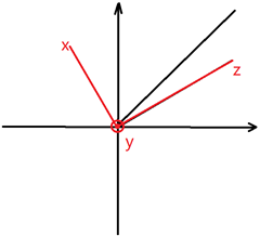 Method Two: Given the three coordinates (Zx,Zy,Zz) of a vector, one vector perpendicular to it has coordinates (Zy,-Zx,0). This likewise gives two mutually perpendicular vectors. Their cross product gives the third vector, producing the three coordinate axes. Arrange the three resulting coordinate-axis vectors in the following form (u is the new x-axis, v is the new y-axis, and w is the new z-axis).
(Note: All three vectors representing the new coordinate axes must be normalized.)
Method Two: Given the three coordinates (Zx,Zy,Zz) of a vector, one vector perpendicular to it has coordinates (Zy,-Zx,0). This likewise gives two mutually perpendicular vectors. Their cross product gives the third vector, producing the three coordinate axes. Arrange the three resulting coordinate-axis vectors in the following form (u is the new x-axis, v is the new y-axis, and w is the new z-axis).
(Note: All three vectors representing the new coordinate axes must be normalized.)
//此为法二的代码,其中Rotation+4等地方用到了指针的技巧
void RotateCoor(float *z,float *Rotation)
{
Rotation[3] = 0;
Rotation[15] = 1;
Normalize(z);
for(int i = 0;i < 3;i++)
Rotation[8+i] = z[i];
Rotation[4] = -z[1];
Rotation[5] = z[0];
Normalize(Rotation+4);
crossproject(z,Rotation+4,Rotation);
Normalize(Rotation);
} The matrix above is the coordinate-system rotation matrix. As with the previous translation and rotation, multiplying this matrix × point P0 gives point P1 after the coordinate axes have been rotated.
Centering a Shape on the Screen and Rotating It About Its Center
1. First, we need to know that the length and width of the dialog box generated by OpenGL can be configured. We need the dialog box’s aspect ratio to match the aspect ratio of the image we want to generate, and the dialog box needs to be slightly larger than the image. 2. The specific idea is as follows: Let the model’s height be ModelHeight and its width be ModelWidth, and let the generated space’s height be h and its width be w. If ModelHeight/h > ModelWidth/w, the dialog box is relatively tall (the model is relatively wide), so the model’s width should be accommodated as much as possible. For example, make the dialog box’s width 2.5 times the model’s width (making the dialog box slightly larger); then the dialog box’s height is the dialog box’s height/model’s height * model’s width. Similarly, a symmetrical conclusion can be obtained when the dialog box is relatively flat. Thus, the calculated dialog-box width and height can be used to generate a suitable dialog box. 3. How to change the dialog-box size programmatically: Open the file used earlier to load the pump-body model (chapt05\shinyjet), and change the ChangeSize function to the following form.
void ChangeSize(int w, int h)
    {
    GLfloat fAspect;
    GLfloat lightPos[] = { -50.f, 50.0f, 100.0f, 1.0f };

    // Prevent a divide by zero
    if(h == 0)
        h = 1;

    // Set Viewport to window dimensions
    glViewport(0, 0, w, h);

    // Reset coordinate system
    glMatrixMode(GL_PROJECTION);
    glLoadIdentity();

    fAspect = (GLfloat) w / (GLfloat) h;
	// Establish clipping volume (left, right, bottom, top, near, far)
	//aspectRatio = (GLfloat)w / (GLfloat)h;
//这之上都不用动
	float scale = 2.5;
//对话框与模型大小比例为2.5倍
	float ScaleHeight,ScaleWidth,ModelWidth,ModelHeight;
//定义对话框的宽高,模型的宽高
	ModelWidth = PointMax[0]-PointMin[0];
	ModelHeight = PointMax[1]-PointMin[1];
//模型宽的计算可由模型上最右的点坐标减最左点的坐标
	if(w*ModelHeight > h*ModelWidth)
	{//当ModelHeight/h > ModelWidth/w时,模型比较宽,对话框比较高
		ScaleHeight = scale * ModelHeight;
//设置对话框的宽为模型宽的2.5倍
		ScaleWidth =  scale * ModelHeight * w / h;
//对话框的高为 对话框的高/模型的高 * 模型的宽
	}
	else
	{
		ScaleWidth =  scale * ModelWidth;
		ScaleHeight = scale * ModelWidth * h / w;
	}
	glOrtho(0.5 * (PointMax[0] - PointMin[0]) - 0.5 * ScaleWidth,0.5 * (PointMax[0] - PointMin[0]) + 0.5 * ScaleWidth,0.5 * (PointMax[1] - PointMin[1]) - 0.5 * ScaleWidth,0.5 * (PointMax[1] - PointMin[1]) + 0.5 * ScaleWidth,-2.0,2.0);
//定出模型的中心坐标,下面代码就根据中心坐标生成一个与模型中心位置相同的对话框
//这之下都不用动
    glMatrixMode(GL_MODELVIEW);
    glLoadIdentity();

    glLightfv(GL_LIGHT0,GL_POSITION,lightPos);
    //glTranslatef(0.0f, 0.0f, -150.0f);
    }
4. How to programmatically find the two diagonally opposite points on the model: Add some code to the while loop previously used to read point coordinates from the file, changing it to the following form.
		while(strcmp(String0,"endsolid"))
		{
			in >> String0;
			in >> n[0] >> n[1] >> n[2];
			in >> String0 >> String0 >> String0 >> Points[0] >> Points[1] >> Points[2];
			in >> String0 >> Points[3] >> Points[4] >> Points[5];
			in >> String0 >> Points[6] >> Points[7] >> Points[8];
//以下为新加内容,作用为找到对角线上的两个点,存到PointMin和PointMax里
			for(float * point = Points + 3;point < Points + 11;point += 3)
			{
				for(int j = 0;j < 3;j++)
				{
					if(Points[j]<PointMin[j])
					{
						PointMin[j] = Points[j];
					}
					if(Points[j]>PointMax[j])
					{
						PointMax[j] = Points[j];
					}
				}
			}
//以上为新加内容
			glColor3ub(255,255,0);
			glBegin(GL_TRIANGLES);
			DrawTriangle(Points,Points+3,Points+6,n);
			glEnd();
			in >> String0 >> String0>> String0;
		}
(注意,因为PointMin和PointMax既在SetupRC函数里使用又在Changesize函数里使用,故需要定义为全局变量,如下float PointMin[3] = {1.0e38f,1.0e38f,1.0e38f};float PointMax[3] = {1.0e-38f,1.0e-38f,1.0e-38f};)
5. Everything now appears ready. We have made the dialog box proportional to the model and aligned their centers of symmetry, but one more issue remains: the center of the generated model and the center of our rotation axis do not coincide. How can we make the model rotate about the origin when a keyboard key is pressed, instead of moving about another axis? The specific idea is that, to rotate the model about its own center, we can first translate the model to the origin of the coordinate axes (so that the origin coincides with the model center), rotate it, and then translate it back to its original position. This makes the model appear to rotate about its own center. The specific code is shown below:
void RenderScene(void)
	{
	// Clear the window with current clearing color
	glClear(GL_COLOR_BUFFER_BIT | GL_DEPTH_BUFFER_BIT);

	// Save the matrix state and do the rotations
	glPushMatrix();

	float Translation[16];
	Translate(0.5f * (PointMax[0] + PointMin[0]),0.5f * (PointMax[1] + PointMin[1]),0.5f * (PointMax[2] + PointMin[2]),Translation);
	glMultMatrixf(Translation);

	glRotatef(xRot,1.0f,0.0f,0.0f);
	glRotatef(yRot,0.0f,1.0f,0.0f);
	Translate(-0.5f * (PointMax[0] + PointMin[0]),-0.5f * (PointMax[1] + PointMin[1]),-0.5f * (PointMax[2] + PointMin[2]),Translation);
	glMultMatrixf(Translation);

	glCallList(DrawList);

	// Restore the matrix state
	glPopMatrix();
	// Display the results
	glutSwapBuffers();
	}
After changing these three places, the model can be displayed correctly in the center of the screen and rotate about its own center.
Chapter 8 Building a Small Vehicle
Assembling a Small Vehicle
Let’s start assembling the small vehicle. Before learning this section, please first master the relevant operations for loading the pump-body model. 1. Principle: We now know how to load and display a model file. The main steps are to first create a new DrawList, then store the model in this list, and finally invoke the list through the glCallList() function to generate a model. What we need to do now is generate many models at the same time. How do we generate many models at once? Simply create many lists and invoke them one by one with glCallList. 2. Since we need to create many lists, it is best to define a function for generating them. Otherwise, copying a large block of code five or six times would make the program exceptionally long. Move the list-creation code from the SetupRC function, modify it slightly, and wrap it in a function. The code for creating a list is explained below. The function’s first parameter is the filename, namely a string such as ""F:\Works\Practice\数字化方法\Shove\Shovel.STL”. The next three parameters are RGB colors used to set the generated model’s color; after all, you would not want the whole vehicle to be one color. The final parameter is the address of the defined list variable, or in other words, a pointer to the list variable. (Note: Why use a pointer? I think this can be understood by referring to last semester’s C++ course. A function’s formal parameters are valid only within its body. For example, if you define a variable in the main function, pass it to another function, and change its value inside that function, the value of the variable in the main function does not change. Therefore, only passing its address allows the list to be created properly.)
void CreatGLList(char *filename,int R,int G,int B,GLuint *listname)
{
	ifstream in(filename);
//要读取的文件是filename,例如如果参数是
//"F:\\Works\\Practice\\数字化方法\\Shove\\Shovel.STL",
//那么会读取F:\\Works\\Practice\\数字化方法\\Shove这个目录下的Shove1.STL文件。
	if (!in)
		_ASSERT(0);

	char String0[30];
	in >> String0 >> String0>> String0;

	*listname = glGenLists(1);
//参数listname是一个指针,*listname才是列表变量
	float Points[12];
	float n[3];

	glNewList(*listname,GL_COMPILE);
		glPolygonMode(GL_BACK,GL_LINE);
		while(strcmp(String0,"endsolid"))
		{
			in >> String0;
			in >> n[0] >> n[1] >> n[2];
			in >> String0 >> String0 >> String0 >> Points[0] >> Points[1] >> Points[2];
			in >> String0 >> Points[3] >> Points[4] >> Points[5];
			in >> String0 >> Points[6] >> Points[7] >> Points[8];
			for(float * point = Points + 3;point < Points + 11;point += 3)
			{
				for(int j = 0;j < 3;j++)
				{
					if(Points[j]<PointMin[j])
					{
						PointMin[j] = Points[j];
					}
					if(Points[j]>PointMax[j])
					{
						PointMax[j] = Points[j];
					}
				}
			}

			glColor3ub(R,G,B);
//根据函数的参数设置模型颜色
			glBegin(GL_TRIANGLES);
			DrawTriangle(Points,Points+3,Points+6);
			glEnd();
			in >> String0 >> String0>> String0;
		}

	glEndList();
}
3. Now that we have a function for creating a new list, can we load files? Not quite. Before using the function, first define several list variables (variables of type GLuint) at the beginning of the file. These variables store the individual models. If you call the function without them, the software will underline the parameters in red because it does not know where to store the loaded models.
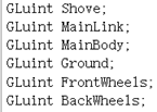 Once these two preparations are complete, we can create and invoke model lists. At the location in SetupRC where the file was previously loaded, a simple call to CreatGLList(“F:\Works\Practice\数字化方法\Shove\Shovel.STL”,255,255,0,&Shove); can replace it. To create six model lists, simply call this function six times, which is much shorter than directly copying a large block of model-loading code. The result is shown below.
 After creating these six model lists, we can invoke them directly. Call glCallList six times in the RenderScene function to invoke all six models.
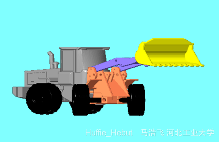
 Invoke the magic dragon—sorry, invoke the models—and they appear directly as an assembled small vehicle. (Although I do not know why either.
That is all for this section.
Invoke the magic dragon—sorry, invoke the models—and they appear directly as an assembled small vehicle. (Although I do not know why either.
That is all for this section.
Making the Small Vehicle Move
The objective of this section is to make the small vehicle move! It is somewhat difficult, so listen carefully while I explain it in detail.
1. Theory: To make this model move when different keyboard keys are pressed, we obviously need a function that reads keypresses and, after reading them, uses matrices for translation, rotation, and similar operations to move the individual parts.
2. Keyboard input: Before writing the function, first define some global variables (the rotation angle of each part) at the beginning of the file for use by the later rotation matrices.
 Next, write the function that reads keypresses. First add the following line to the main function at the bottom. This is a library function used to read keypresses.
 Then define a function named keyboard earlier in the file. Its body consists of repeated code.
void keyboard(unsigned char key,int x,int y)
{
	static float ShoveStep = 3.0f;
//定义一个静态变量(下一次进入函数,变量内容保持不变)
//步长为3.0f,即设定按一下按键角度变化3度
	if(ShoveRot > 60.0f)
		ShoveRot = -3.0f;
	else if(ShoveRot < -60.0f)
		ShoveRot = 3.0f;
//这里作用是防止模型出现失真(比如铲子转着转着转到驾驶舱里去了)
	switch(key)
	{
		case 'w':ShoveRot+=ShoveStep;glutPostRedisplay();break;
		case 's':ShoveRot-=ShoveStep;glutPostRedisplay();break;
	}
//判断是否是“某一按键”,是的话相应部分的转动角度增加(减少)一个步长。
	static float MainLinkStep = 3.0f;
	if(MainLinkRot > 60.0f)
		MainLinkRot = -3.0f;
	else if(MainLinkRot < -60.0f)
		MainLinkRot = 3.0f;
	switch(key)
	{
		case 'a':MainLinkRot+=MainLinkStep;glutPostRedisplay();break;
		case 'd':MainLinkRot-=MainLinkStep;glutPostRedisplay();break;
	}

	static float MainBodyStep = 3.0f;
	if(MainBodyRot > 60.0f)
		MainBodyRot = -3.0f;
	else if(MainBodyRot < -60.0f)
		MainBodyRot = 3.0f;
	switch(key)
	{
		case 'j':MainBodyRot+=MainBodyStep;glutPostRedisplay();break;
		case 'k':MainBodyRot-=MainBodyStep;glutPostRedisplay();break;
	}

	static float GroundStep = 3.0f;
	if(GroundRot > 60.0f)
		GroundRot = -3.0f;
	else if(GroundRot < -60.0f)
		GroundRot = 3.0f;
	switch(key)
	{
		case 'q':GroundRot+=GroundStep;glutPostRedisplay();break;
		case 'e':GroundRot-=GroundStep;glutPostRedisplay();break;
	}
	static float FrontWheelsStep = 3.0f;
	if(FrontWheelsRot > 60.0f)
		FrontWheelsRot = -3.0f;
	else if(FrontWheelsRot < -60.0f)
		FrontWheelsRot = 3.0f;
	switch(key)
	{
		case 'z':FrontWheelsRot+=FrontWheelsStep;glutPostRedisplay();break;
		case 'x':FrontWheelsRot-=FrontWheelsStep;glutPostRedisplay();break;
	}
	static float BackWheelsStep = 3.0f;
	if(BackWheelsRot > 60.0f)
		BackWheelsRot = -3.0f;
	else if(BackWheelsRot < -60.0f)
		BackWheelsRot = 3.0f;
	switch(key)
	{
		case 'c':BackWheelsRot+=BackWheelsStep;glutPostRedisplay();break;
		case 'v':BackWheelsRot-=BackWheelsStep;glutPostRedisplay();break;
	}

}
We have now successfully read the keypresses and can change the corresponding angle variable according to the key pressed. (You can configure the keys in the function to suit your preferences.) 3. Matrix operations First, consider how several functions are used: glLoadIdentity(); generates an identity matrix and sets it as the current matrix. glPushMatrix(); saves the current matrix in an unspecified location. glPopMatrix(); sets the previously saved matrix as the current matrix. glMultMatrixf(A); multiplies the current matrix by matrix A and sets the result as the current matrix. glRotatef(angle value,0.0f,1.0f,0.0f); for the final three parameters, if the first is 1, rotation is about the x-axis; if the second is 1, rotation is about the y-axis; and if the third is 1, rotation is about the z-axis. There is also a translation library function that I cannot remember.
void RenderScene(void)
	{
	// Clear the window with current clearing color
	glClear(GL_COLOR_BUFFER_BIT | GL_DEPTH_BUFFER_BIT);

	// Save the matrix state and do the rotations
	glPushMatrix();

	Translate(0.5f * (PointMax[0] + PointMin[0]),0.5f * (PointMax[1] + PointMin[1]),0.5f * (PointMax[2] + PointMin[2]),Translation);
	glMultMatrixf(Translation);

	glRotatef(xRot,1.0f,0.0f,10.0f);
	glRotatef(yRot,0.0f,1.0f,0.0f);
	Translate(-0.5f * (PointMax[0] + PointMin[0]),-0.5f * (PointMax[1] + PointMin[1]),-0.5f * (PointMax[2] + PointMin[2]),Translation);
	glMultMatrixf(Translation);

	glPushMatrix();
	glCallList(MainBody);

	glPopMatrix();
	glPushMatrix();
	Translate(0,float(-4.89/1000.0),float(-39.75/1000.0),Translation);
	glMultMatrixf(Translation);
	Rotate_x(ShoveRot,Rotation);
	glMultMatrixf(Rotation);
	Translate(0,float(4.89/1000.0),float(39.75/1000.0),Translation);
	glMultMatrixf(Translation);
	glCallList(BackWheels);

	glLoadIdentity();
	Translate(0.5f * (PointMax[0] + PointMin[0]),0.5f * (PointMax[1] + PointMin[1]),0.5f * (PointMax[2] + PointMin[2]),Translation);
	glMultMatrixf(Translation);
	glRotatef(xRot,1.0f,0.0f,10.0f);
	glRotatef(yRot,0.0f,1.0f,0.0f);
	Translate(-0.5f * (PointMax[0] + PointMin[0]),-0.5f * (PointMax[1] + PointMin[1]),-0.5f * (PointMax[2] + PointMin[2]),Translation);
	glMultMatrixf(Translation);
	glPushMatrix();
	Translate(0,float(-6.63/1000.0),float(16.50/1000.0),Translation);
	glMultMatrixf(Translation);
	Rotate_x(ShoveRot,Rotation);
	glMultMatrixf(Rotation);
	Translate(0,float(6.63/1000.0),float(-16.50/1000.0),Translation);
	glMultMatrixf(Translation);
	glCallList(FrontWheels);

    glPopMatrix();
	Translate(0,0,float(-10/1000.0),Translation);
	glMultMatrixf(Translation);
	glRotatef(GroundRot,0.0f,1.0f,0.0f);
	Translate(0,0,float(10/1000.0),Translation);
	glMultMatrixf(Translation);
	glCallList(Ground);

	Translate(0,float(21.74/1000),float(4.06/1000.0),Translation);
	glMultMatrixf(Translation);
	Rotate_x(MainLinkRot,Rotation);
	glMultMatrixf(Rotation);
	Translate(0,float(-21.74/1000),float(-4.06/1000.0),Translation);
	glMultMatrixf(Translation);
	glCallList(MainLink);

	Translate(0,float(31.74/1000.0),float(53.46/1000.0),Translation);
	glMultMatrixf(Translation);
	Rotate_x(ShoveRot,Rotation);
	glMultMatrixf(Rotation);
	Translate(0,float(-31.74/1000.0),float(-53.46/1000.0),Translation);
	glMultMatrixf(Translation);
	glCallList(Shove);

	// Restore the matrix state
	glPopMatrix();
	// Display the results
	glutSwapBuffers();
	}
All of this code can be obtained from the Netdisk link at the beginning of the article.
 (2) The main body and the two wheels must be separated from (1), because their displacements have no cumulative relationship. This can be implemented with glPushMatrix(); and glPopMatrix();.
I do not understand this part of the program very thoroughly myself. If you have questions or do not understand it, please contact me separately.
(2) The main body and the two wheels must be separated from (1), because their displacements have no cumulative relationship. This can be implemented with glPushMatrix(); and glPopMatrix();.
I do not understand this part of the program very thoroughly myself. If you have questions or do not understand it, please contact me separately.
Continue……
Comments