[Note-Taking Tools] Markdown Syntax and the Obsidian Editor
An introduction to Markdown, the powerful note-taking syntax I have long used, and Obsidian, an editor based on Markdown syntax.
113 posts
An introduction to Markdown, the powerful note-taking syntax I have long used, and Obsidian, an editor based on Markdown syntax.
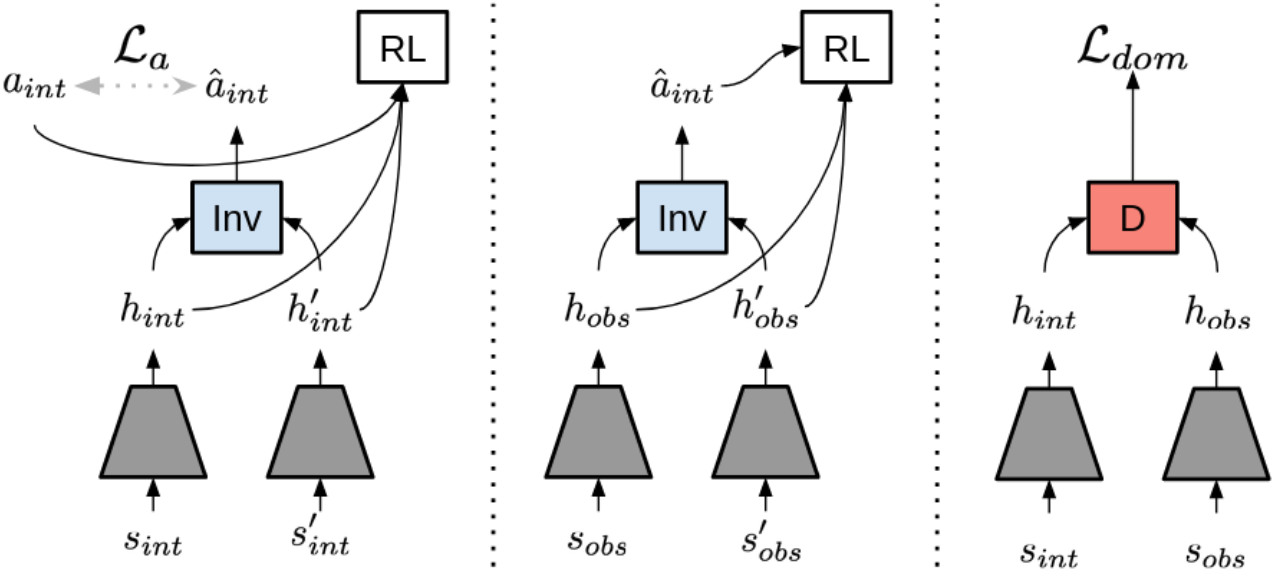
Survey and notes on reinforcement learning-based robot motion imitation methods.
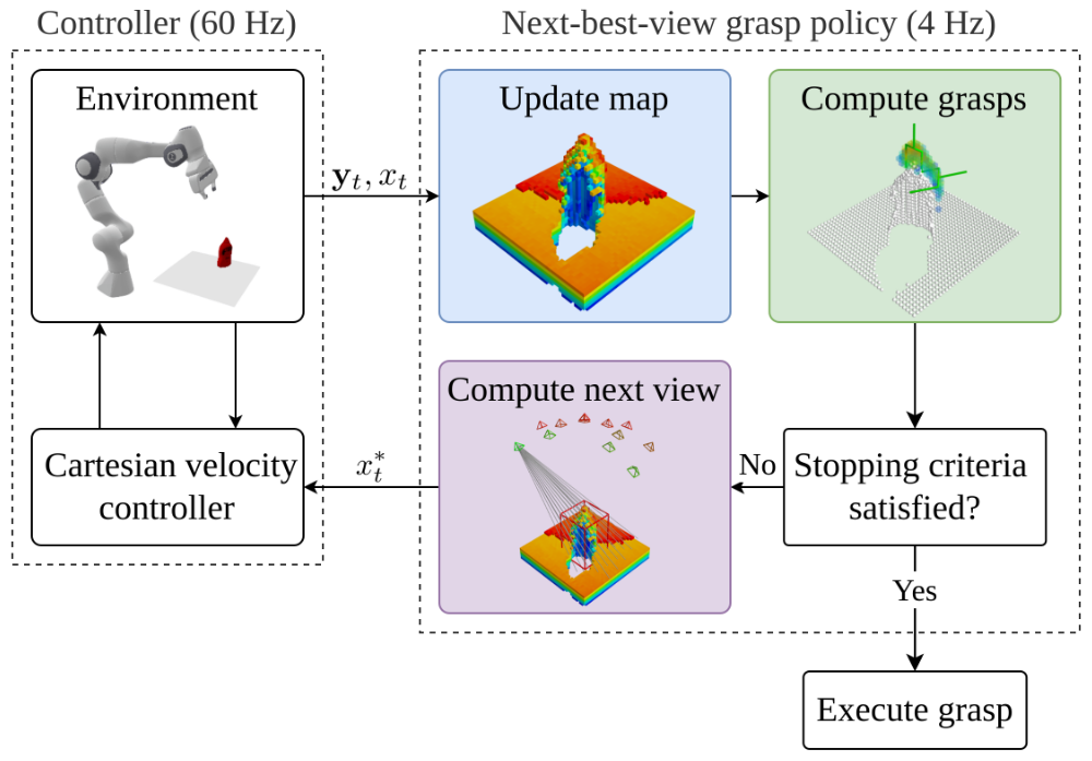
A survey of grasp pose estimation papers from top conferences and journals over the past three years
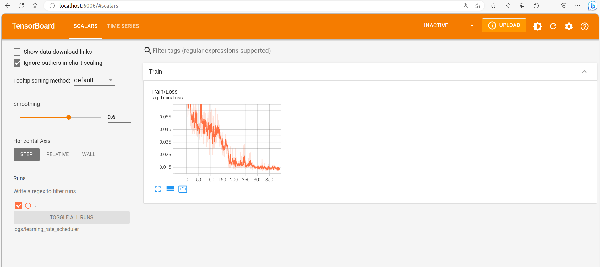
During deep learning training, we inevitably need to observe changes in metrics such as Loss and Learning_rate, so plotting curves in real time is essential. This article explains how to use PyTorch's TensorBoard to plot curves.
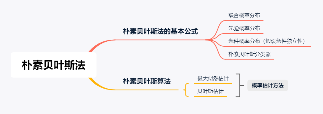
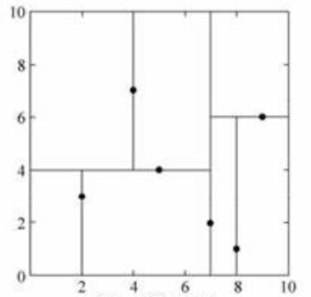
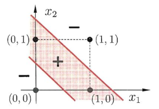
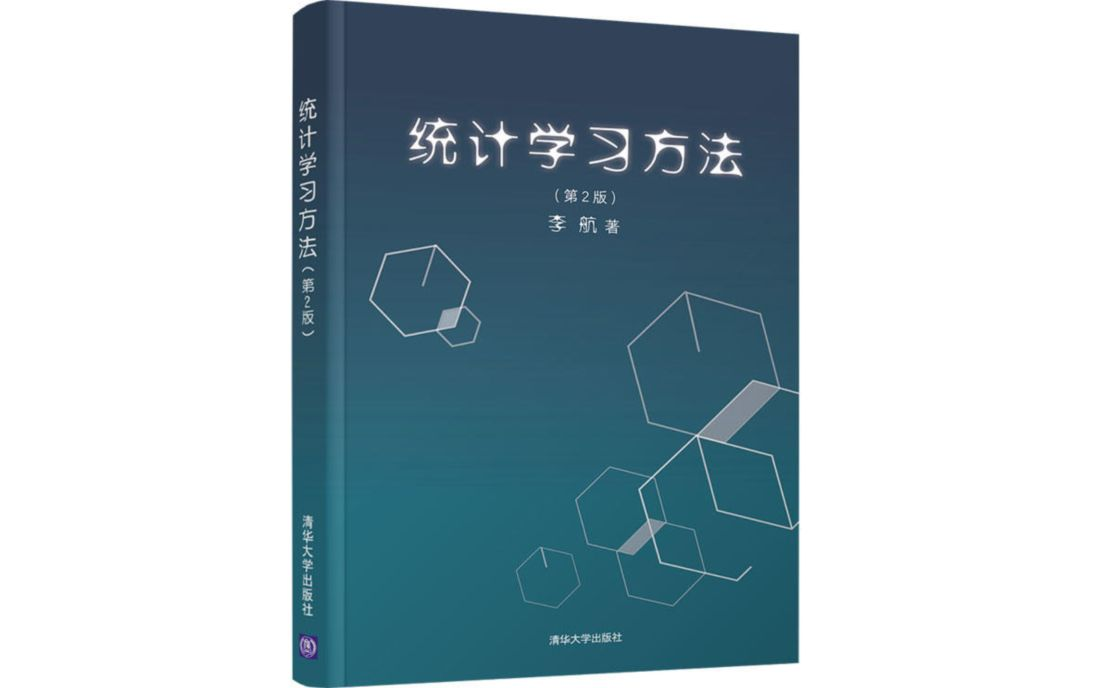
Study notes on Statistical Learning Methods
Environment setup can be tedious, and many programs' dependency environments can conflict with the local environment. Docker is a good way to avoid these issues.
Because some projects were developed some time ago, their programs use opencv2, while most people now have opencv4 installed. Since these projects contain a lot of code, modifying the source code would be too cumbersome, therefore considering installing multiple opencv versions side by side.
The nearest neighbors algorithm assumes a training dataset is given in which the class of each instance is known. For classification, a new instance is predicted from the classes of its k nearest training instances by majority voting or similar rules. Therefore, the k-nearest neighbors method has no explicit learning process.
The perceptron is a linear binary classification model. Its input is an instance's feature vector, and its output is the instance's class. Its goal is to find a separating hyperplane that linearly divides the training data.
Statistical learning is the discipline in which computers build probabilistic and statistical models from data and use those models to predict and analyze data. These notes follow Li Hang's book *Statistical Learning Methods*.
FFB6D fuses RGB and point cloud information during the feature extraction stage, then performs instance segmentation and keypoint detection.
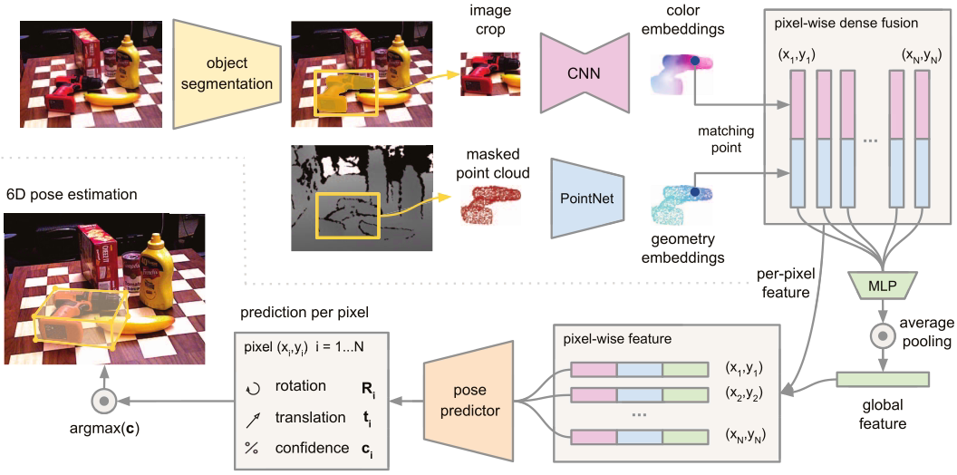
This paper proposes a heterogeneous architecture that processes two data sources (RGB and depth maps) separately and uses a novel dense fusion network to extract dense pixel-level features for pose estimation.
Attempted to test PVNet but gave up partway through.
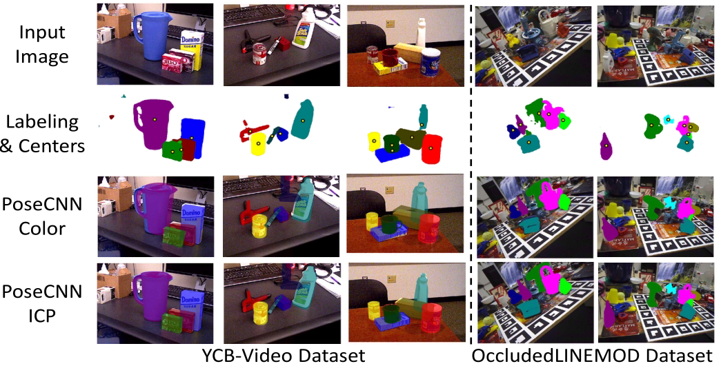
Addresses the increased difficulty of 6D pose estimation caused by occlusion and clutter between objects by combining a backbone network with ICP point matching.
ROS is essential for robot software development, while Qt is essential for graphical user interfaces. This article explains how to use ROS libraries in Qt.
Introduces modal and non-modal dialogs in Qt, as well as standard dialogs.
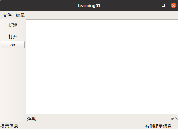
Introduces how to implement QMainWindow features, including the menu bar, toolbar, status bar, dock widgets, central widget, and more.
Covers Qt basics and walks through creating your first Qt program (an empty window with a button). Introduces signals and slots, and implements the simplest case—closing the window when a button is pressed.
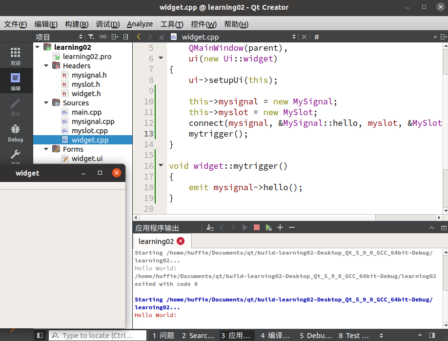
Signals and slots are among the most important concepts in Qt. They enable signal transmission between senders and receivers and form the basis of various Qt operations.
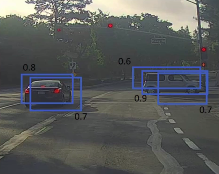
Basic implementation methods for object detection, starting with object localization and summarizing object detection algorithms such as landmark detection, object detection, the sliding-window method, and NMS (Non-Max Suppression).
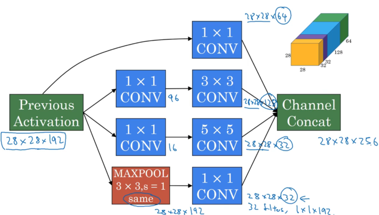
This article introduces several classic neural network models, including the network architectures of LeNet-5, AlexNet, VGG-16, ResNet, Inception networks, and more.
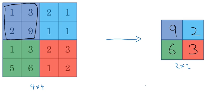
Why do neural networks often use convolution when analyzing images? Why are there padding and stride? What roles do pooling layers and fully connected layers play?
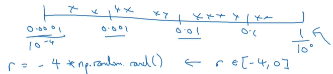
This article introduces common parameter-selection principles and approximate ranges in neural networks, as well as the basic principles of BN and softmax.
The LineMod algorithm was proposed by Hinterstoisser et al. in 2011. Using template matching, it addresses real-time detection and 6D pose estimation and localization for low-texture three-dimensional objects in cluttered scenes.
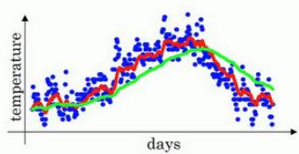
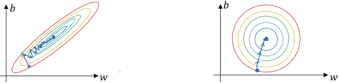
This article introduces several of the most commonly used optimization algorithms, starting from partitioning the dataset into mini-batches, then covering momentum gradient descent, RMSprop, and their combination Adam, along with implementation details and basic principles for each method.
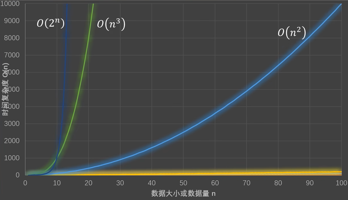
Explains concepts such as O(n) in time complexity and how to calculate time complexity.
There are many ways to improve neural network training performance, such as avoiding underfitting and overfitting, using regularization, and so on. Different methods also have different effects.
Linear regression in deep learning, basic optimization algorithms, and implementations of Softmax regression and loss functions.
Introduces how to perform basic data operations with PyTorch and pandas, and how to carry out fundamental linear algebra operations and derivative computation with torch.
Notes from configuring Ubuntu after installation. I recently set up dual-boot systems and also tinkered with a Raspberry Pi; here is a summary.
Python has a rich set of useful built-in modules and third-party modules that make it quick and convenient to implement many common features.
This article summarizes basic Python file reading and writing operations, as well as common os operations on directories and files, such as retrieving paths, joining paths, renaming files, and moving files. It also summarizes commonly used JSON operations.
During program execution, you inevitably encounter all kinds of errors. Some are caused by bugs in the code, some by user input, and others are completely unpredictable at runtime. Python includes a built-in exception-handling mechanism to help us handle errors.
Summarizes basic class usage; the characteristics and application examples of encapsulation, inheritance, and polymorphism; and inheritance-oriented advanced features such as multiple inheritance and customized classes.
In Python, less code is better, and simpler code is better. Based on this philosophy, Python provides many useful advanced features, such as list comprehensions, generators, anonymous functions, and decorators.
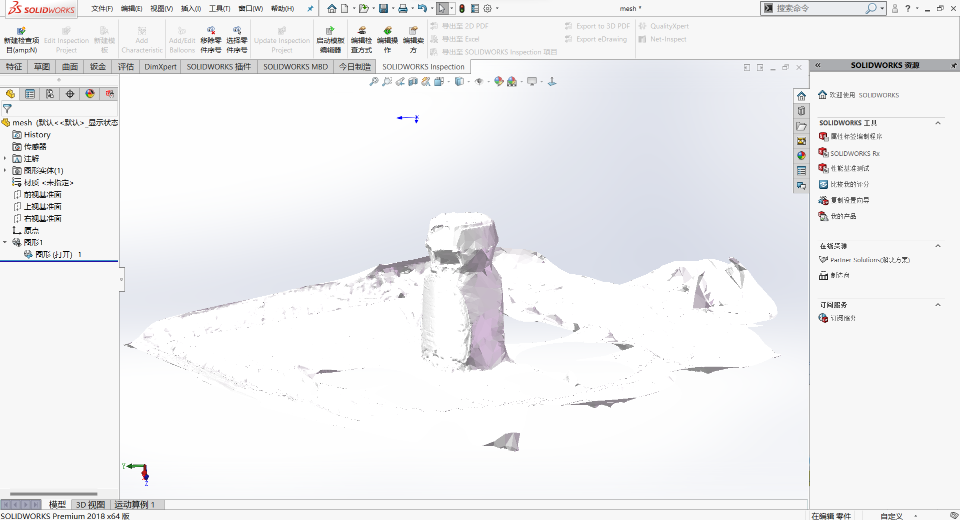
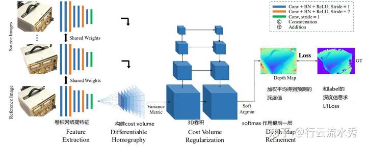
Three-dimensional reconstruction uses a camera to photograph real-world objects and scenes, then processes them with computer vision techniques to obtain a three-dimensional model of the object. The main techniques involved include multi-view stereo, depth map estimation, point cloud processing, mesh reconstruction and optimization, texture mapping, Markov random fields, image segmentation, and more.
Notes from my journey learning deep learning from scratch. This chapter introduces the most fundamental mathematical ideas behind deep learning, as well as simple regression-based approaches to deep learning algorithms and related code.
A summary of some concepts that beginners may find difficult to understand when starting out in deep learning.
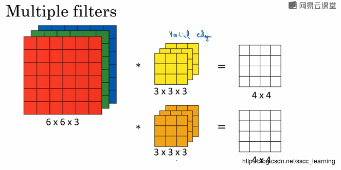
Generally, channels refers to the number of convolution kernels in each convolutional layer. The channels of the initial input image sample depend on the image type, such as RGB; after convolution, out_channels depends on the number of convolution kernels. The out_channels then also serves as the in_channels of the convolution kernel in the next convolution.

Convolution is essentially the process of taking a matrix of a specific size each time, sliding it across the input matrix, and computing the inner product at each position.
Notes and examples on functions and methods for array operations with NumPy, including array creation, slicing and indexing, basic array operations (transposing, joining, sorting, flattening, and more), and the use of some basic array computation functions.
We may want to install many different versions of Python on a computer, or we may want a Python environment to contain only the packages we use so it is easier to package and distribute a program. These situations all require creating Python virtual environments. Anaconda is a tool for managing Python environments like this.
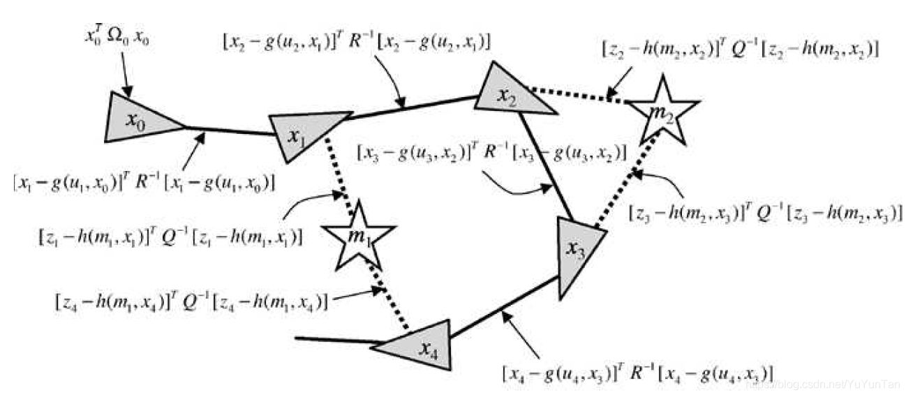
g2o (General Graph Optimization) is a graph optimization library that combines nonlinear optimization with graph theory. We can use g2o to solve any least-squares problem that can be represented as graph optimization.
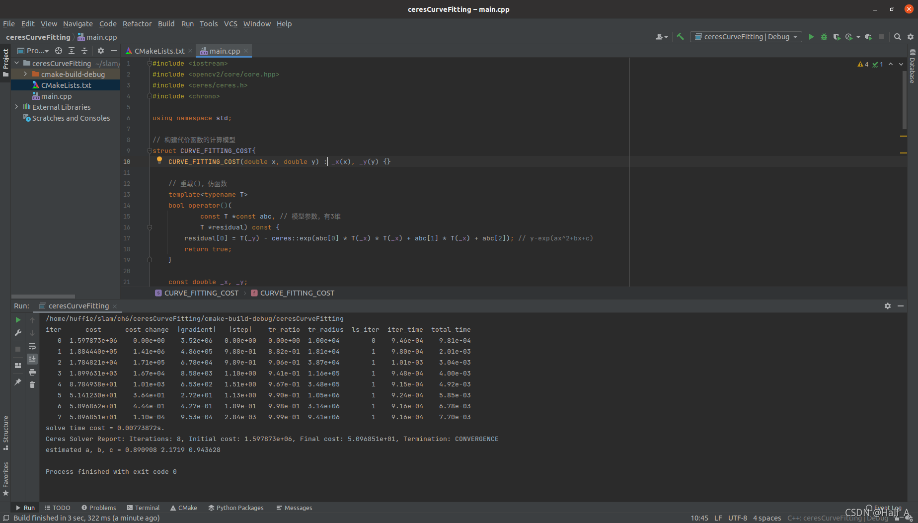
Ceres is a library for solving least-squares problems. We only need to define the problem to be optimized and let it perform the computation. Usage: 1. Define each parameter block. A parameter block is simply a vector, but it can also have a special structure such as a quaternion or Lie algebra……
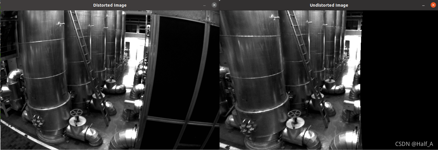
This article first introduces the imaging principle of pinhole cameras and the conversion between physical coordinates and pixel coordinates. It then introduces a distortion model based on real-world camera issues, presents undistortion formulas, and includes a detailed example program.
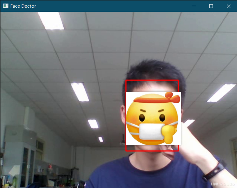
First, download all the files in `opencv/samples/dnn/face_detector/` from OpenCV's GitHub site and overwrite the files in the local directory. Then open weights.meta4 in Notepad and download the files corresponding to the two URLs it contains.
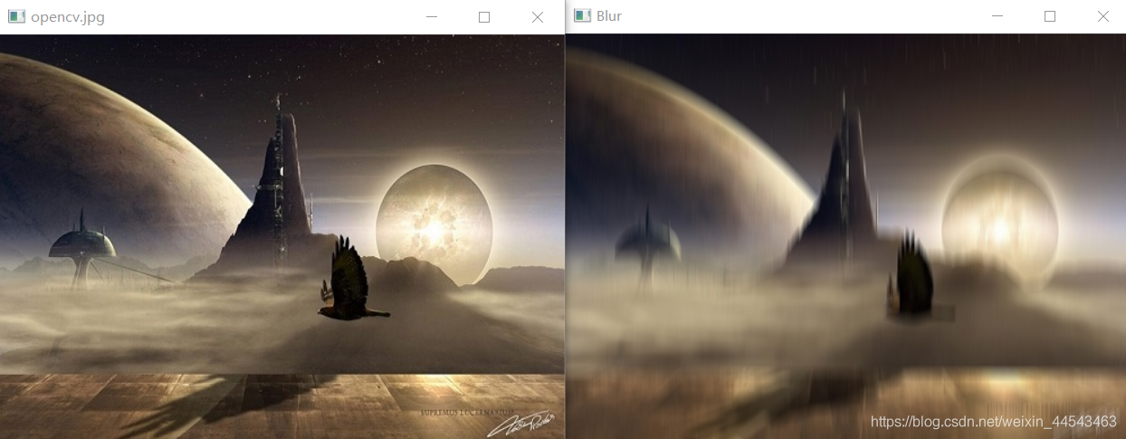
Mean filtering uses the principle of image convolution. As shown in the figure below, when the convolution kernel is a third-order unit matrix, mean filtering is performed: each third-order submatrix of the original image has its mean computed and assigned to the center element.
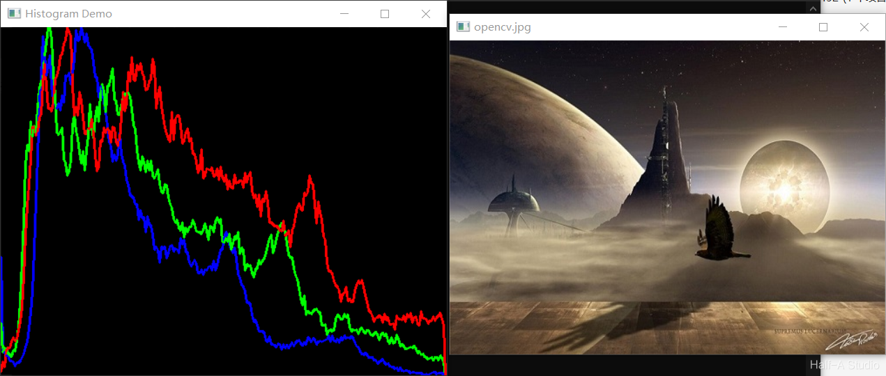
An image histogram is a statistical feature of image pixel values. It is inexpensive to compute and has many advantages, including invariance to image translation, rotation, and scaling. It is widely used across image processing, especially for grayscale image thresholding, color-based image retrieval, image classification, and backprojection tracking. Common types are grayscale histograms and color histograms.
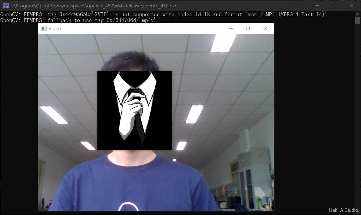
Reading and processing video is essential in image processing. In OpenCV, the main function used to read camera video is capture(). This article explains how to read camera video with OpenCV and describes the functions used to save it, including their implementation and specific details.
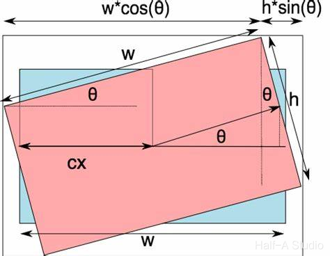
Common image transformation methods include image scaling, flipping, and rotation. In OpenCV, each of these image transformation operations has a corresponding function. This article introduces various image transformation methods through explanations of function definitions and concrete examples.
Normalization constrains the data to be processed, after processing (via some algorithm), within a certain range. This makes later data processing easier and also helps the program converge faster during runtime.
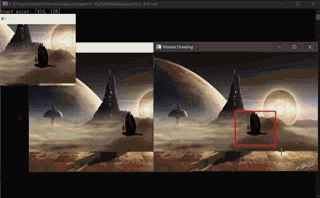
This article introduces how to handle keyboard and mouse input in OpenCV, the functions involved, and the parameters of each function. It also uses keyboard and mouse input handling to create several interesting small programs.
C and C++ provide the rand() and srand() functions for generating random numbers, and they can also be used when writing OpenCV code in C++. OpenCV also provides its own RNG class for generating random numbers, which is very convenient to use. This article mainly introduces how to use RNG and how to draw random lines based on the random numbers it generates.
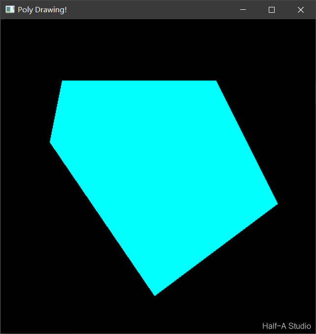
This article introduces methods for drawing rectangles, circles, lines, and ellipses with C++ and OpenCV 4. It focuses on the definitions of OpenCV built-in functions (such as rectangle(), circle(), line(), and ellipse()) and the role of each parameter, and provides example programs for reference. It also summarizes methods for drawing polygons, including the polygon-border drawing function polylines(), the polygon-filling function fillPoly(), the function for drawing multiple polygons drawContours(), and more.
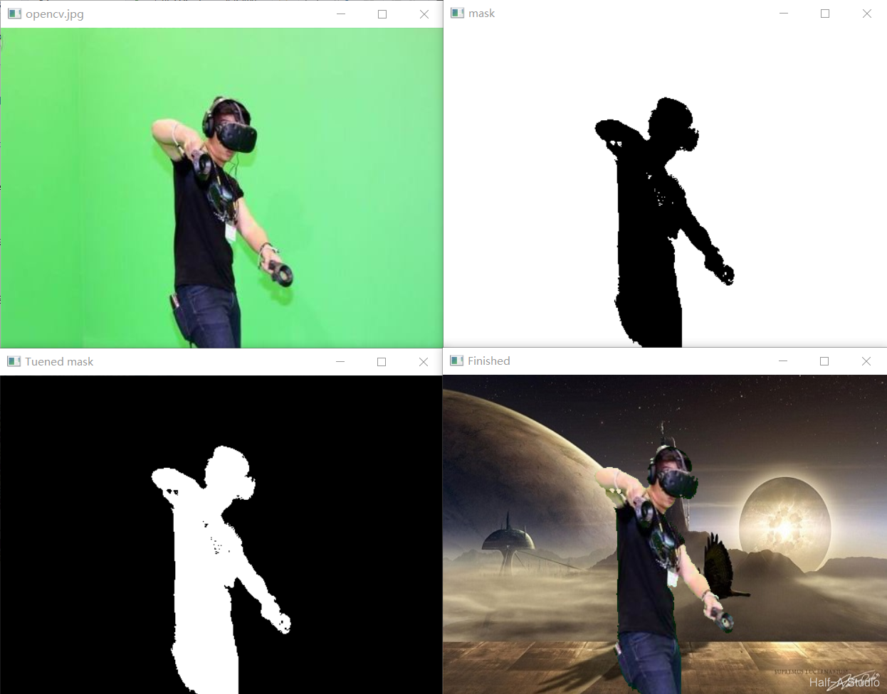
Replacing the background of a green-screen image involves ① color-space conversion, ② extracting the green-screen region, ③ inverting the green-screen region, and ④ copying the image. The various functions and code encountered along the way are also covered in detail in this article.
After splitting image channels, the output multi-channel sequence is typically stored using std::vector mv;, where mv[0], mv[1], and mv[2] correspond to the three BGR channels respectively. However, what is displayed now is essentially three single-channel images—in other words, three grayscale images. To restore intuitive color to the three images, you need to use the channel merging method described below.
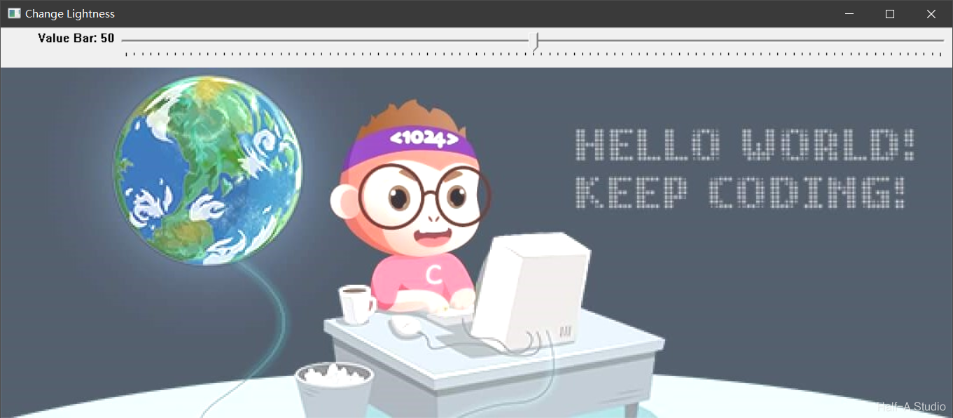
OpenCV uses createTrackbar() to create a Trackbar. The function syntax and the purpose of each parameter are shown below.
Image pixel operations include read and write operations, arithmetic operations, logical operations, and more. Pixel operations are not only diverse; operations on grayscale images and color images also have their own characteristics. Operating on pixels allows us to access every pixel in an image and implement many unexpected functions.
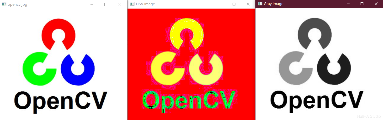
Color space conversion function: cvtColor. GRAY: grayscale, with only one Channel for the grayscale value. BGR: the BGR color space, based on the three primary colors red, green, and blue (0~255), which are combined to form various colors. HSV: the hexagonal cone model, with Hue measured in degrees (0~180), Saturation in the range 0 ~ 255, and Value in the range 0 ~ 255.
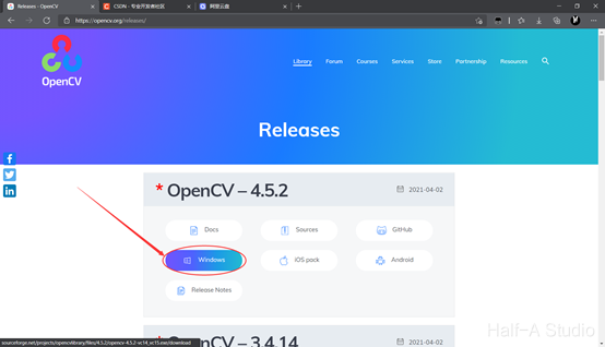
First, download and extract OpenCV. I recommend downloading the Windows installer from the official OpenCV website. If the download is too slow, I have also uploaded the OpenCV4.5.2 installer to Aliyun Drive at https://www.aliyundrive.com/s/VGkaM7vyuck. Make sure to extract it to an English-only path.
Eigen is an open-source C++ linear algebra library that provides fast matrix and linear algebra operations, equation solving, and other features. Many higher-level software libraries also use Eigen for matrix operations. Eigen is a header-only library, so to use it, you only need to include its header files; no library linking is required.
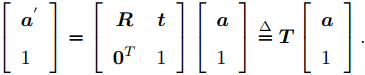
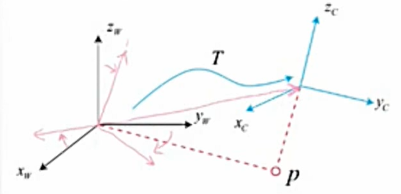
The rotation and translation between two coordinate frames are collectively called the transformation between frames. While a robot moves, we often define an inertial frame (the world frame), which can be treated as fixed. The robot itself is a moving frame.
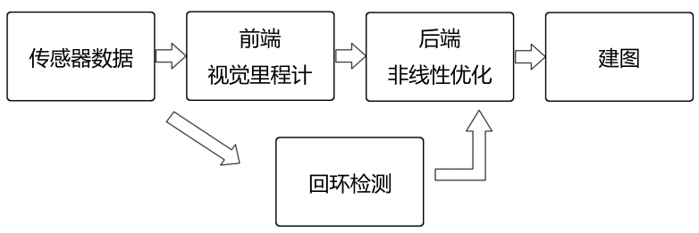
For a mobile robot, we often need it to know two things—where it is (localization) and what the surrounding environment looks like (mapping).
An element can move freely within a box and overlap other boxes. When the window is scrolled, some modules stay fixed at a certain position on the screen. Neither of these effects can be achieved quickly with standard flow or floats alone; positioning is needed in those cases.
Emmet was formerly known as Zen Coding. It uses abbreviations to speed up HTML/CSS coding, and VS Code has built-in support for it.
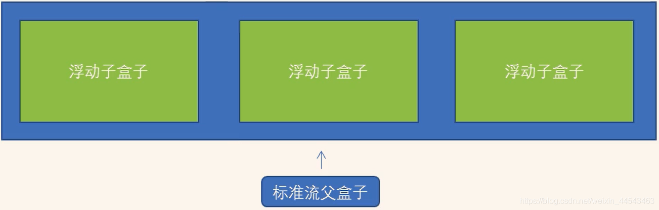
CSS provides three traditional layout methods—normal flow (standard flow), floats, and positioning. All three are used to arrange boxes. Once the boxes are placed in the appropriate positions, the layout naturally takes shape. In actual development, a page generally includes all three layout methods (mobile devices have newer layout methods).
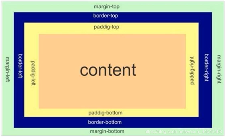
Web page layout learning has three core topics—the box model, floats, and positioning. Learning the box model helps us lay out pages well. The web page layout process: first prepare the related page elements, use CSS to set the box styles, then place them in the corresponding positions, and put content into the boxes.
CSS classifies selectors by type as basic selectors and composite selectors. Composite selectors are built by combining basic selectors. CSS background properties can add background styles to elements on a page, including background colors, images, tiling, image positions, and fixed background images.
CSS is mainly used to beautify web pages and lay them out. Web pages look unattractive when only HTML is used. CSS is also a markup language, mainly used to set the text content (font, size, alignment, etc.), the appearance of images (width and height, border styles, margins, etc.), and the layout and visual styles of HTML pages.
HTML is a language used to describe web pages. HTML stands for HyperText Markup Language. HTML is not a programming language; it is a markup language. How to use HTML headings, paragraphs, links, and images. Elements, attributes, and formatting; links, styles, and tables; how to create lists, blocks, layouts, and forms.
Data generated while a program is running is temporary and is released once the program finishes. Files can be used to persist data. File operations in C++ require an #include directive.
Inheritance is one of the three core features of object-oriented programming. When defining a class, a lower-level class shares the common characteristics of the level above while also having its own characteristics.
Operator overloading redefines existing operators to give them another function, allowing them to work with different data types. This article covers overloading the addition, left-shift, increment, assignment, relational, and function-call operators.
Some private members may need to be accessed by certain functions or classes outside the class, which requires friends. The keyword for friends is fiend. Friends can be implemented in three ways: a global function as a friend, a class as a friend, or a member function as a friend.
In C++, a class's member variables and member functions are stored separately, and only non-static member variables belong to objects of the class. Each non-static member function has only one function instance, meaning that multiple objects of the same type share one block of code. How does the code distinguish which object invoked it? This is where the this pointer comes in.
Every object needs initial setup and cleanup before it is destroyed. Object initialization and cleanup are two very important safety concerns. Using an object or variable without an initial state has unknown consequences; failing to clean up an object or variable in time after use can also cause safety issues.
Encapsulation combines attributes and behaviors into a whole to represent real-world entities, while controlling access to those attributes and behaviors. When designing a class, attributes and behaviors are written together to represent an entity. The syntax is as follows.
In C++, parameters in a function's parameter list can have default values. If an argument is passed to a parameter, the supplied value is used; otherwise, the default value is used. However, if a parameter at a given position has a default argument, every parameter after it must also have a default value.
Rviz is a three-dimensional visualization tool that is highly compatible with robot platforms based on the ROS software framework. Rviz can graphically display robot sensor data, robot motion status, environmental information, and more.
The functions of a laubch file are as follows: it configures and starts multiple nodes through an XML file. It can also start ROS Master automatically (so there is no need to run roscore separately).
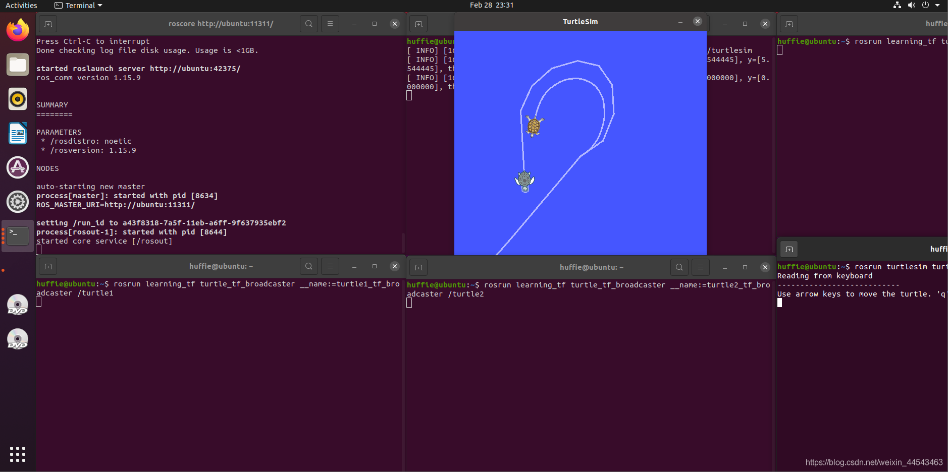
The TF package manages all coordinate frames. It keeps a ten-second history of the relationships among all frames and can show where a grasped object is relative to the robot's center frame.
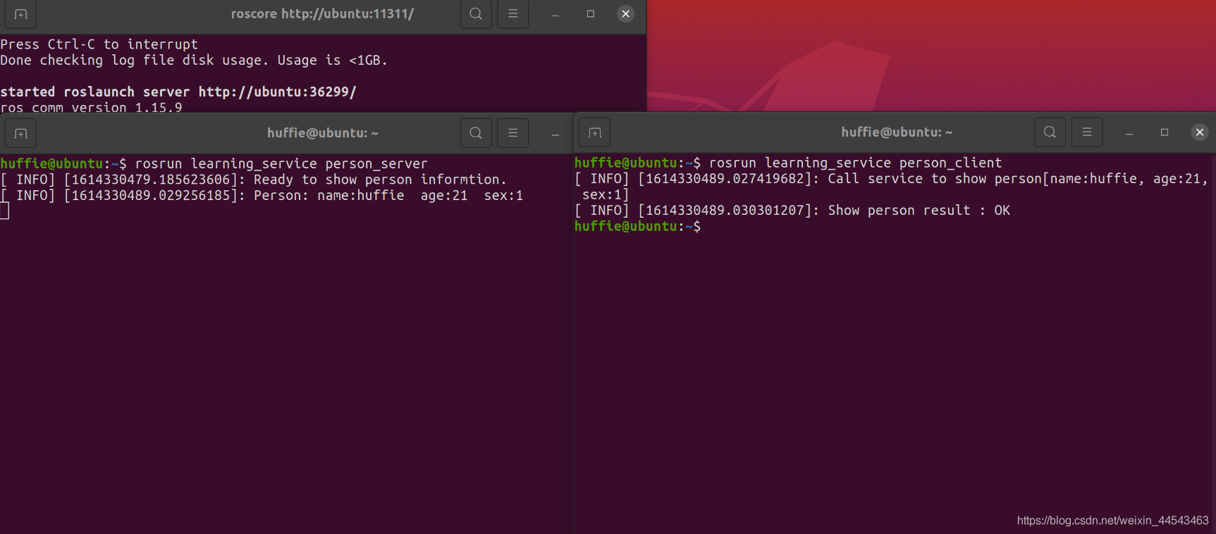
Each time the Client makes one Request, the Server sends data once. The data format is personal information such as name, gender, and so on.
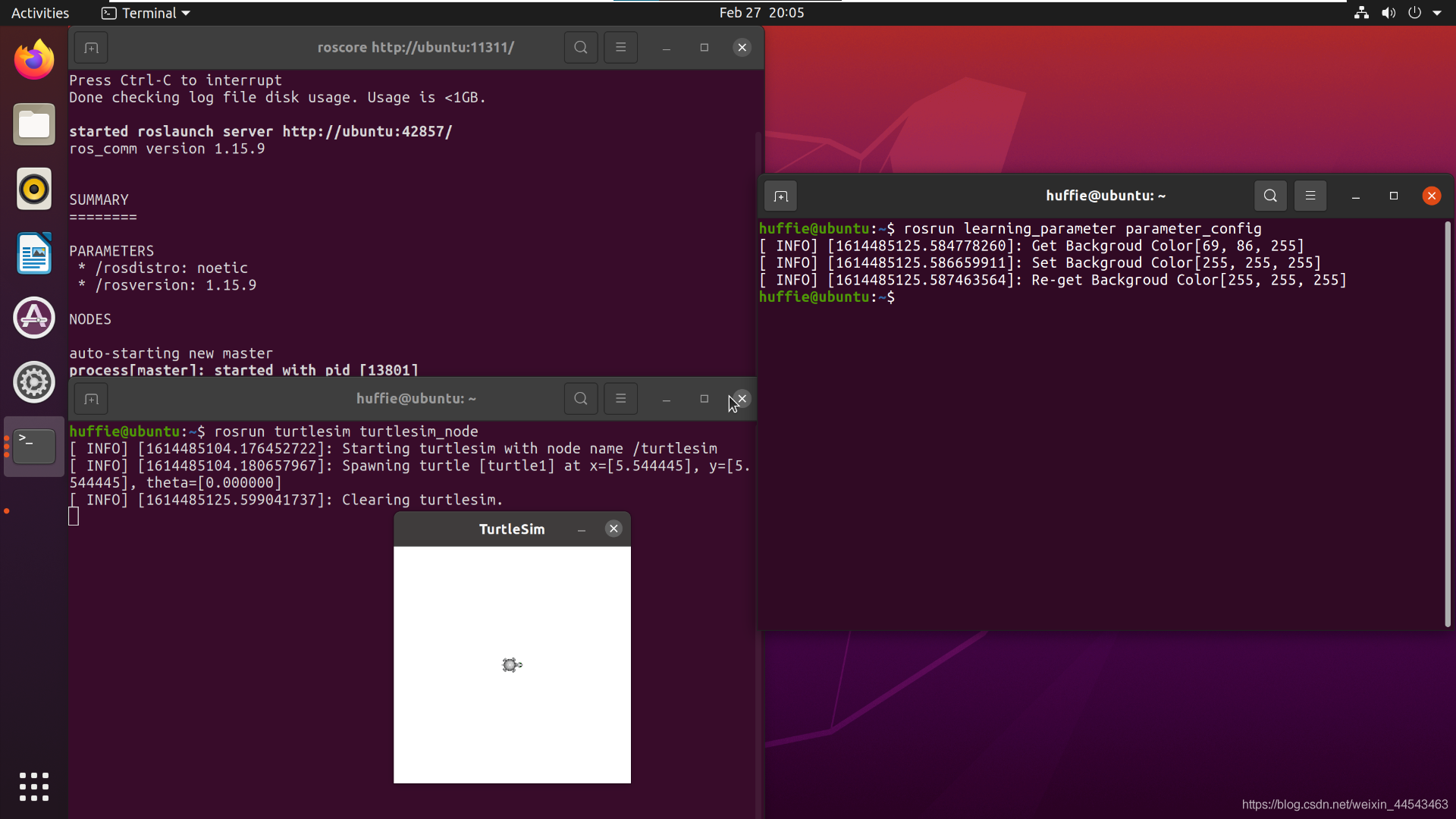
ROS Master includes a Parameter Server, which is a global dictionary that stores configuration parameters. These configuration parameters are globally accessible to all nodes.
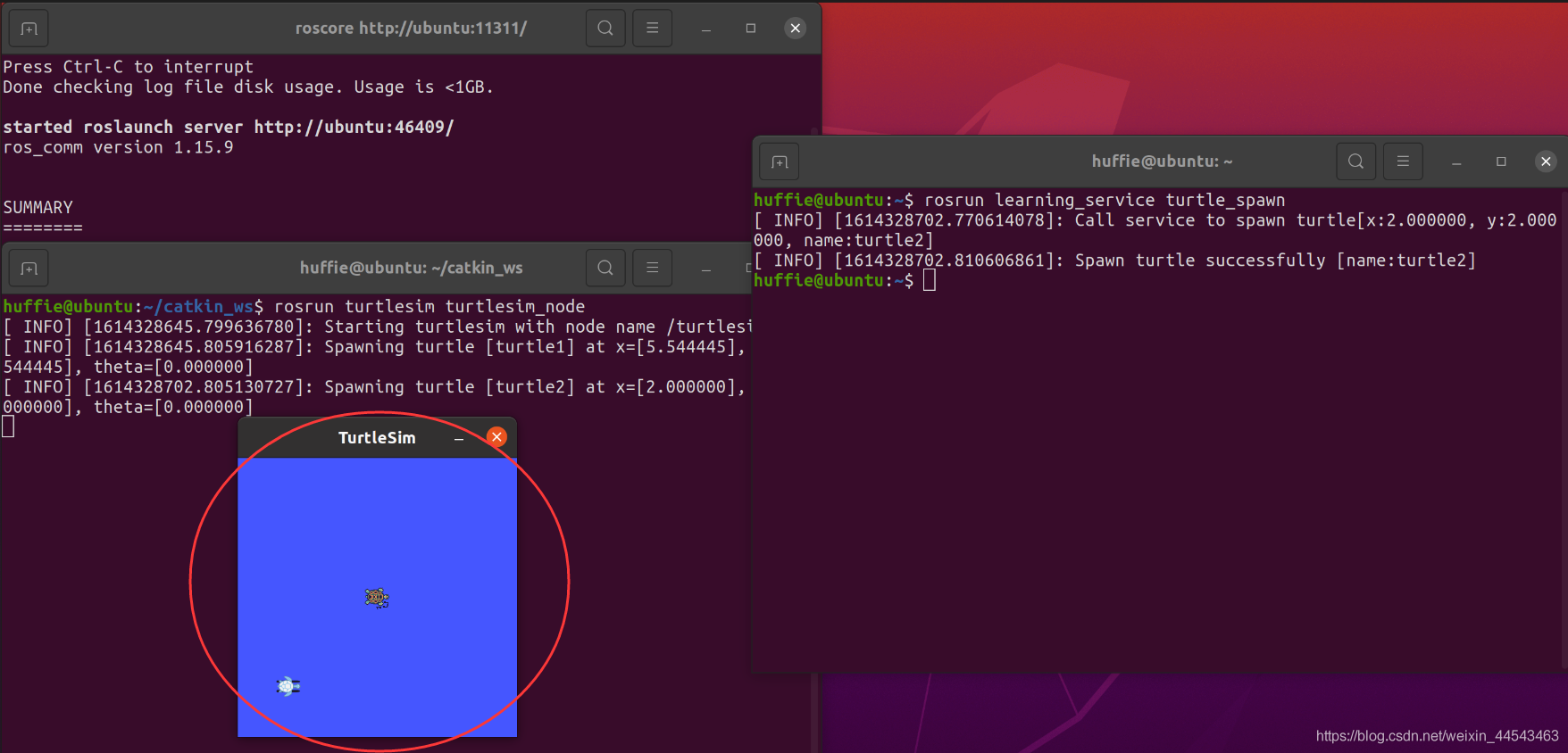
Send a service request programmatically. In other words, the client sends a request to the server to spawn a turtle, and the server returns the response to the client. Go back to the catkin_ws/src directory and create a package named learning_service.
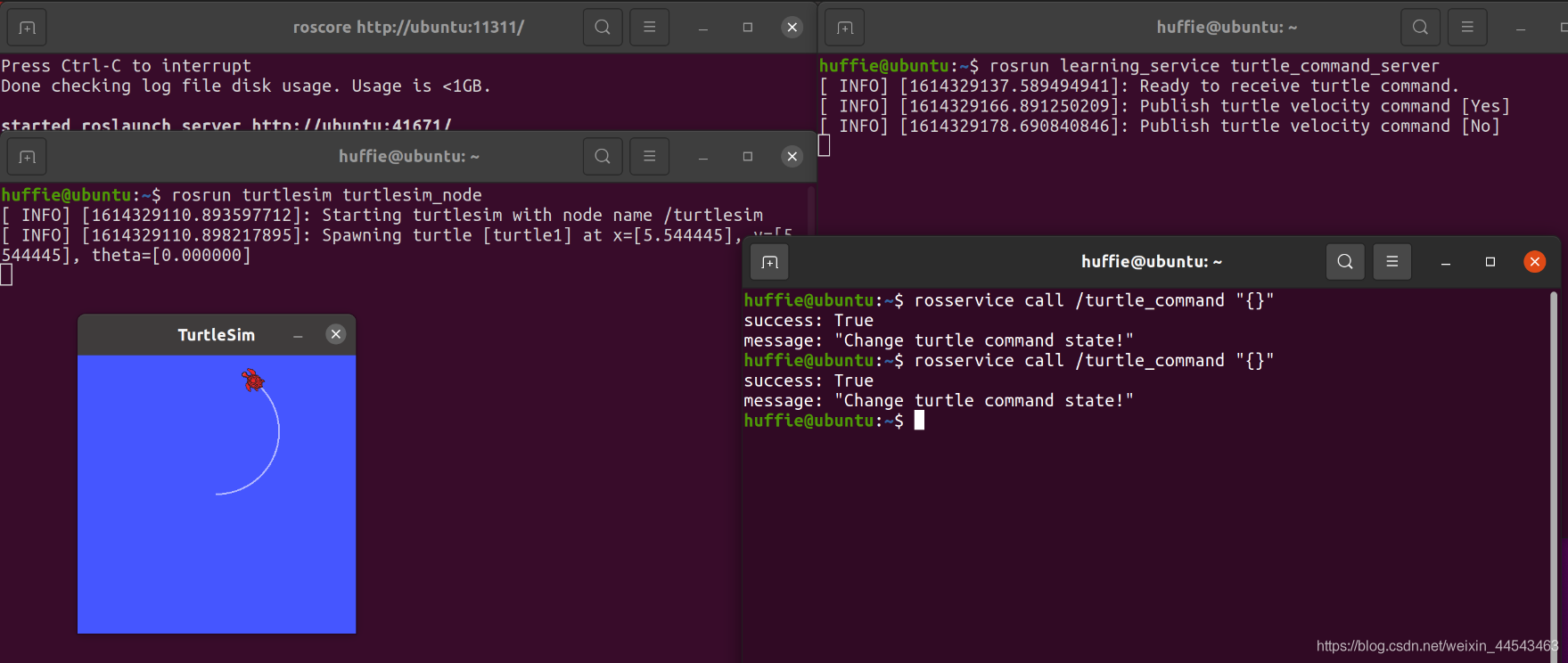
The server waits for a signal. Each time it receives a signal from the client, it toggles the turtle's motion state (moving → stopped, stopped → moving).
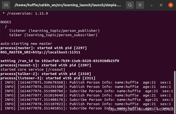
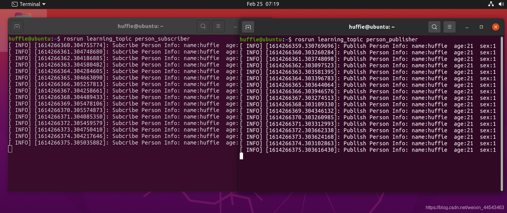
In ROS Master, you can publish and subscribe to predefined messages, such as information about a turtle's motion and pose. However, sometimes you need to define custom message types. The main objective of this section is to define a Person message containing personal information, publish it through a Publisher, and subscribe to it through a Subscriber.
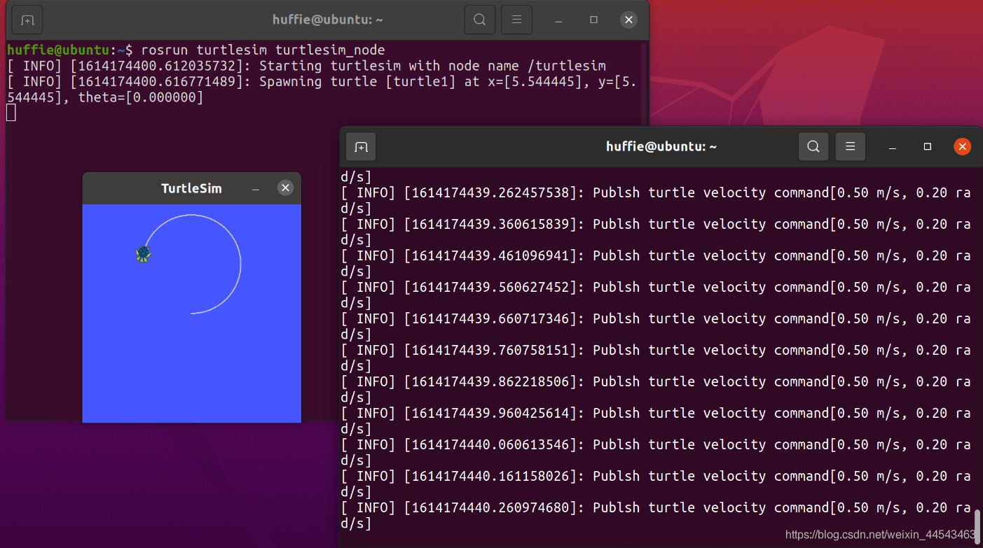
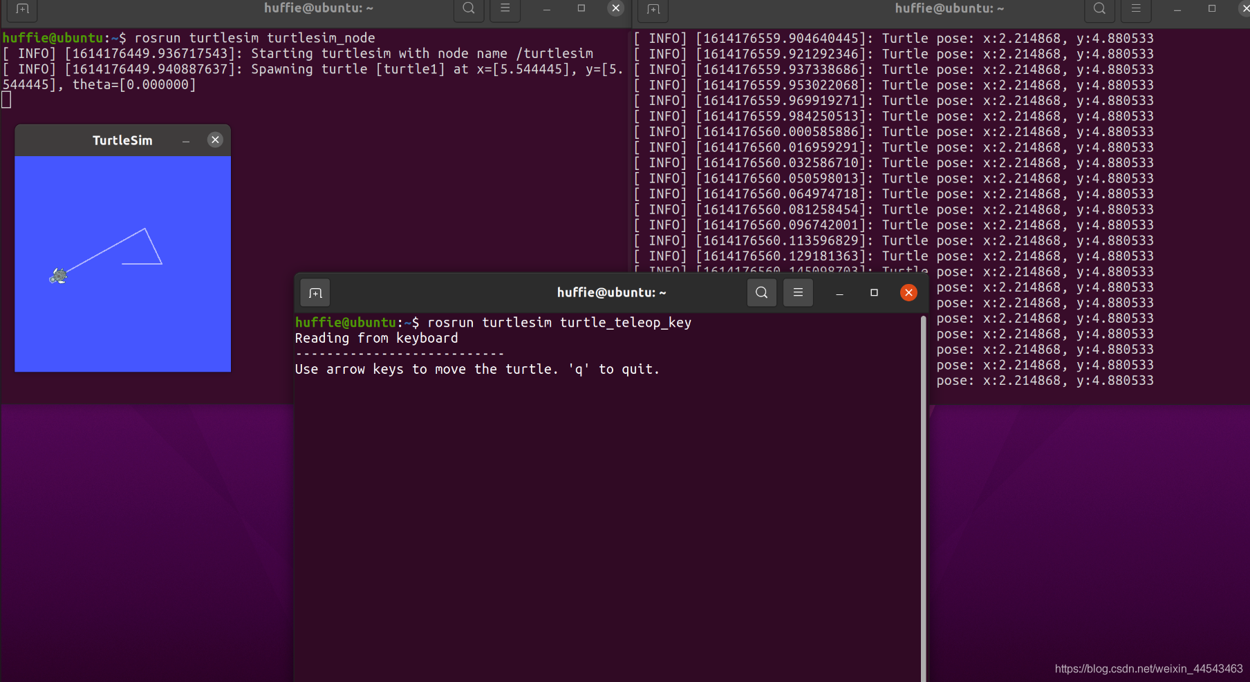
ROS Master contains two nodes: a Subscriber (turtlesim) and a Publisher. The Publisher is implemented in code to publish a Message containing linear velocity and angle. The Message is transmitted through a Topic channel to the Subscriber, thereby controlling the turtle's movement.
In ROS_Master, you can publish and subscribe to messages. ROS_Master contains two nodes: a Subscriber (turtlesim) and a Publisher. The Publisher publishes Messages programmatically. The Message content includes linear velocity and angle, and it is passed to the Subscriber through the Topic pipeline, thereby controlling the turtle's movement.
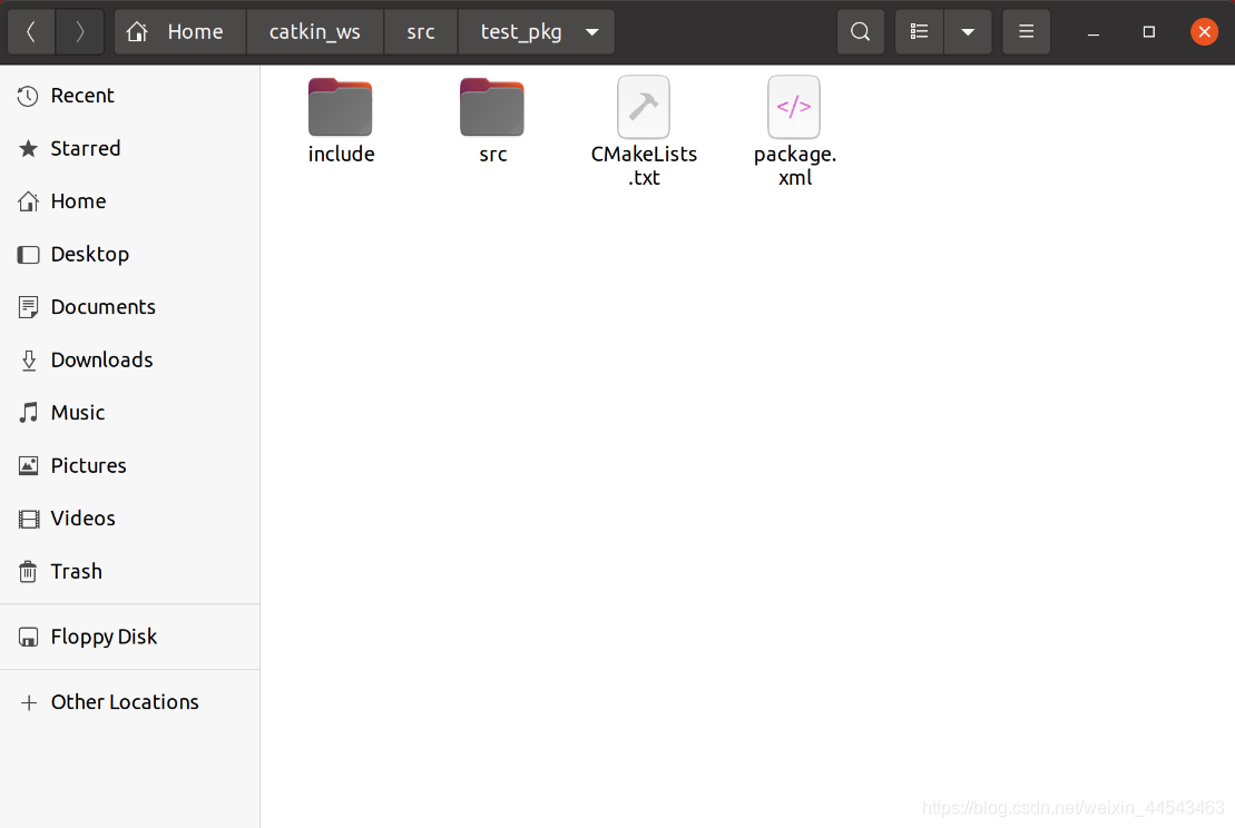
A workspace is a folder that holds project development files, similar to a project you create in an IDE on Windows. Folders in a workspace include …
roscore starts ROS Master and is the first command to run before starting a ROS system; rosrun runs a node in a package. It takes two arguments: the package name first and the node name second.
When a program is relatively complex, or when repeated sections appear within a program, modular program design is often a viable approach. In RobotStudio, you can call different routines from the main program to keep the code logic clear.
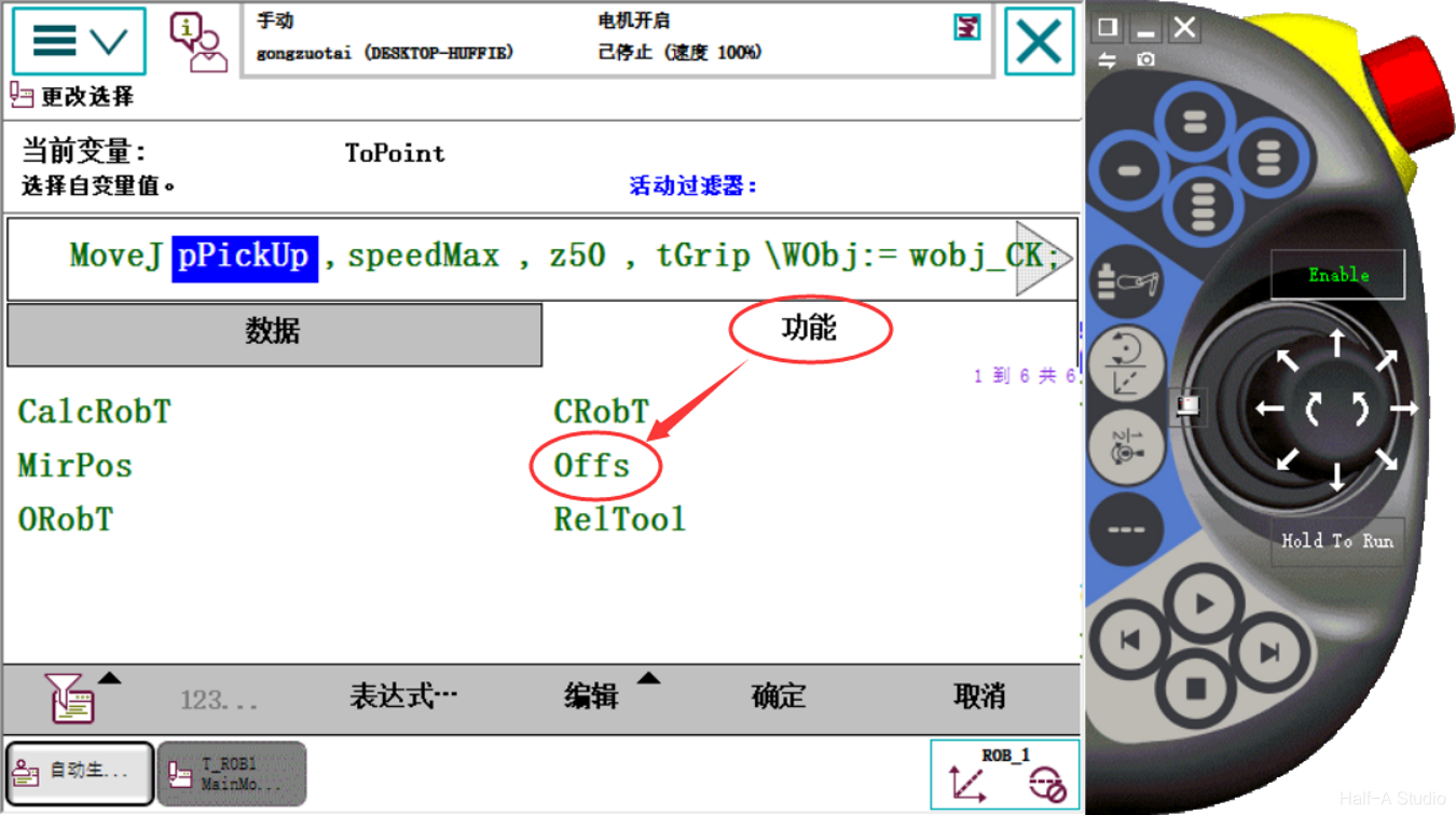
The Offs instruction offsets coordinates based on the currently selected workobject coordinate system and a reference point. Click the robtarget data to offset and select Function - Offs to configure the coordinate offset.
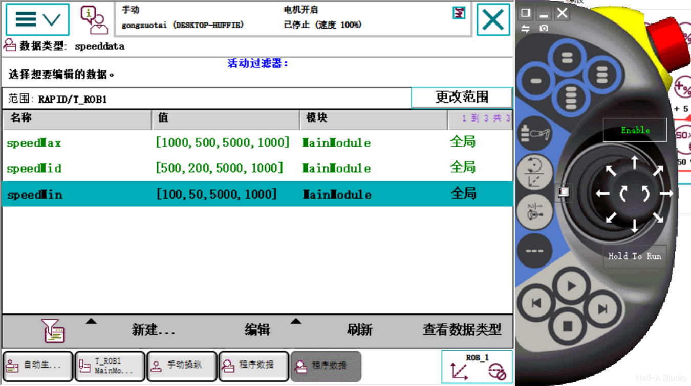
In manual mode, the maximum speed is limited to 250mm/s. The v1000 speed used in a program is very fast both in simulation and on a physical robot, so the robot's motion speed and delay time need to be configured.
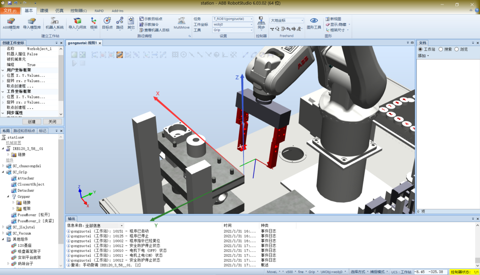
Create a Cartesian coordinate system at any position and orientation on the target workbench; this is called a WorkObject coordinate system. By creating WorkObject coordinate systems at different locations, the same program can perform the same process at those different locations.
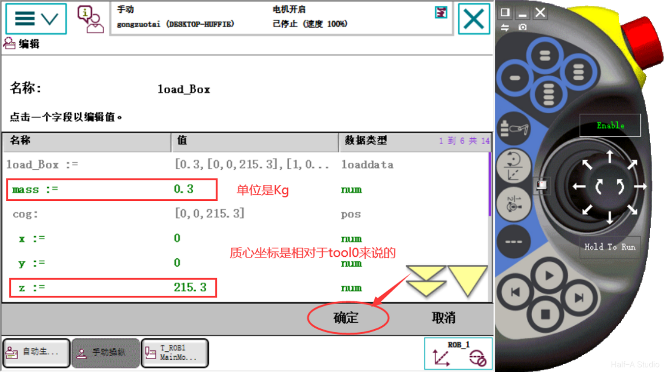
After the gripper picks up a workpiece, the system load changes. This difference may not be obvious in a simulation, but it must be taken into account in a real system.
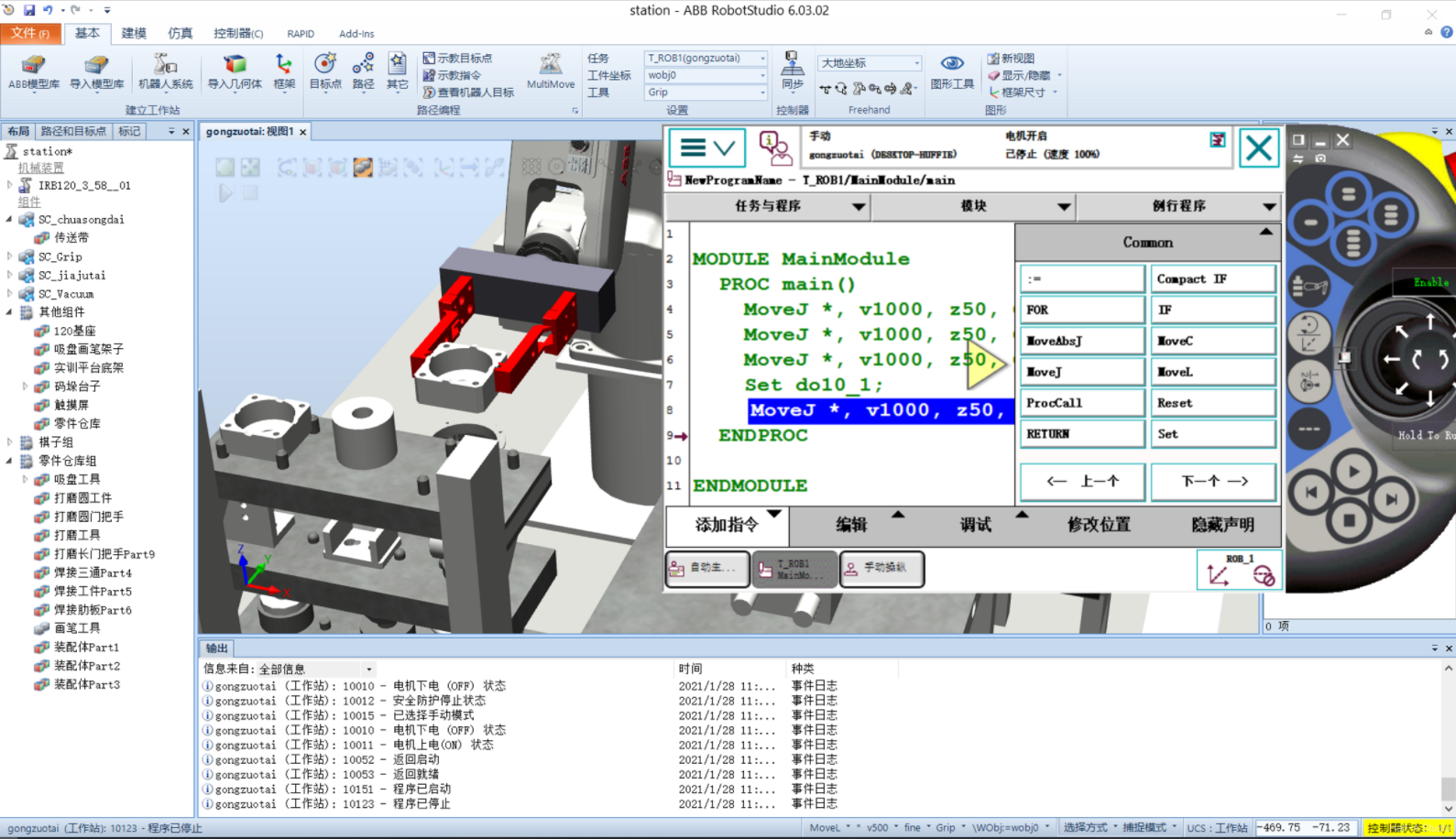
MoveJ moves the robot to a position. Set/Reset controls external devices. Add a MoveJ instruction at the initial position to move the robot gripper directly above the workpiece, then add another MoveJ instruction (adding a waypoint above the workpiece prevents the robot from grasping directly and possibly colliding with the workpiece from the side).
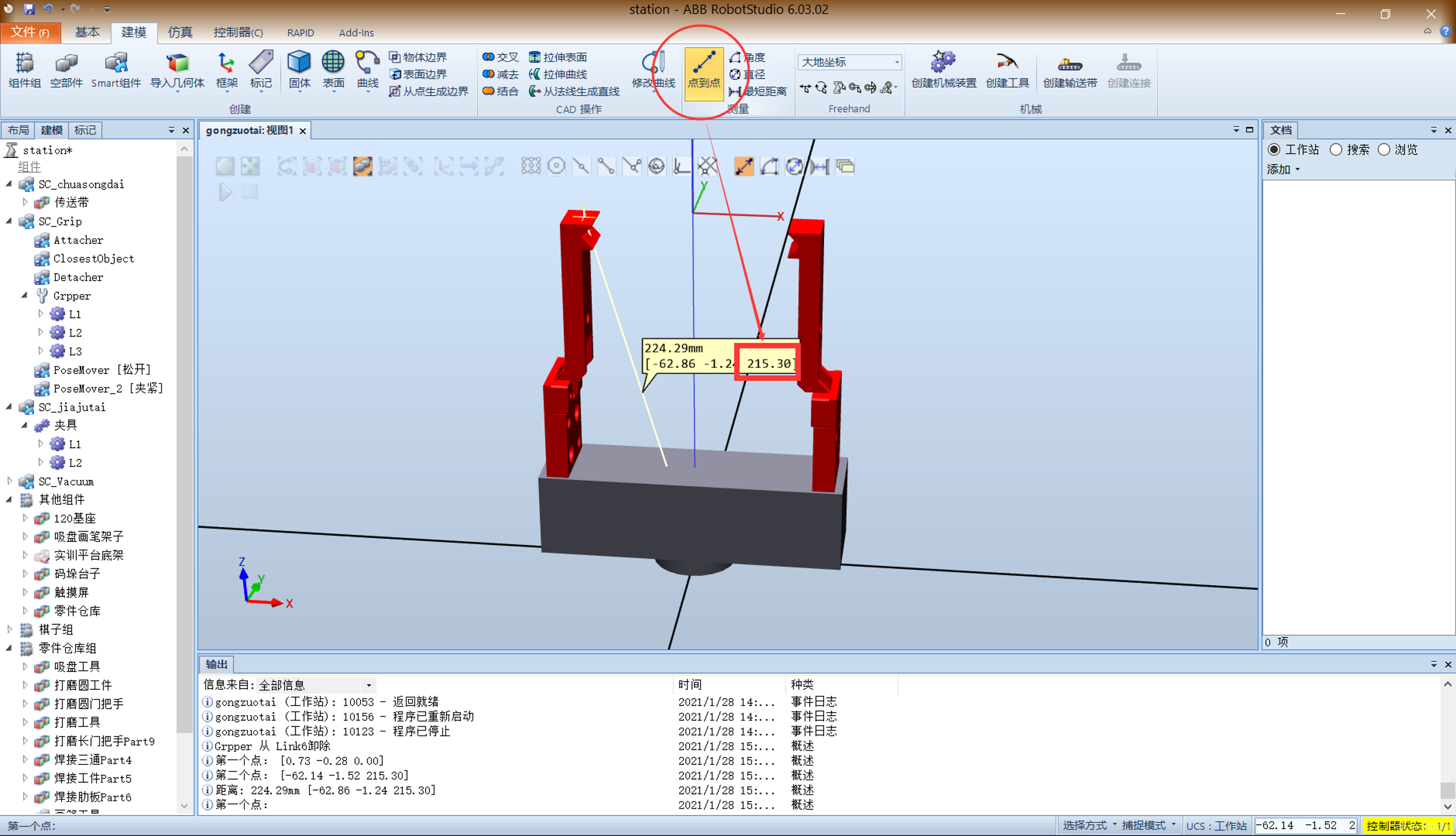
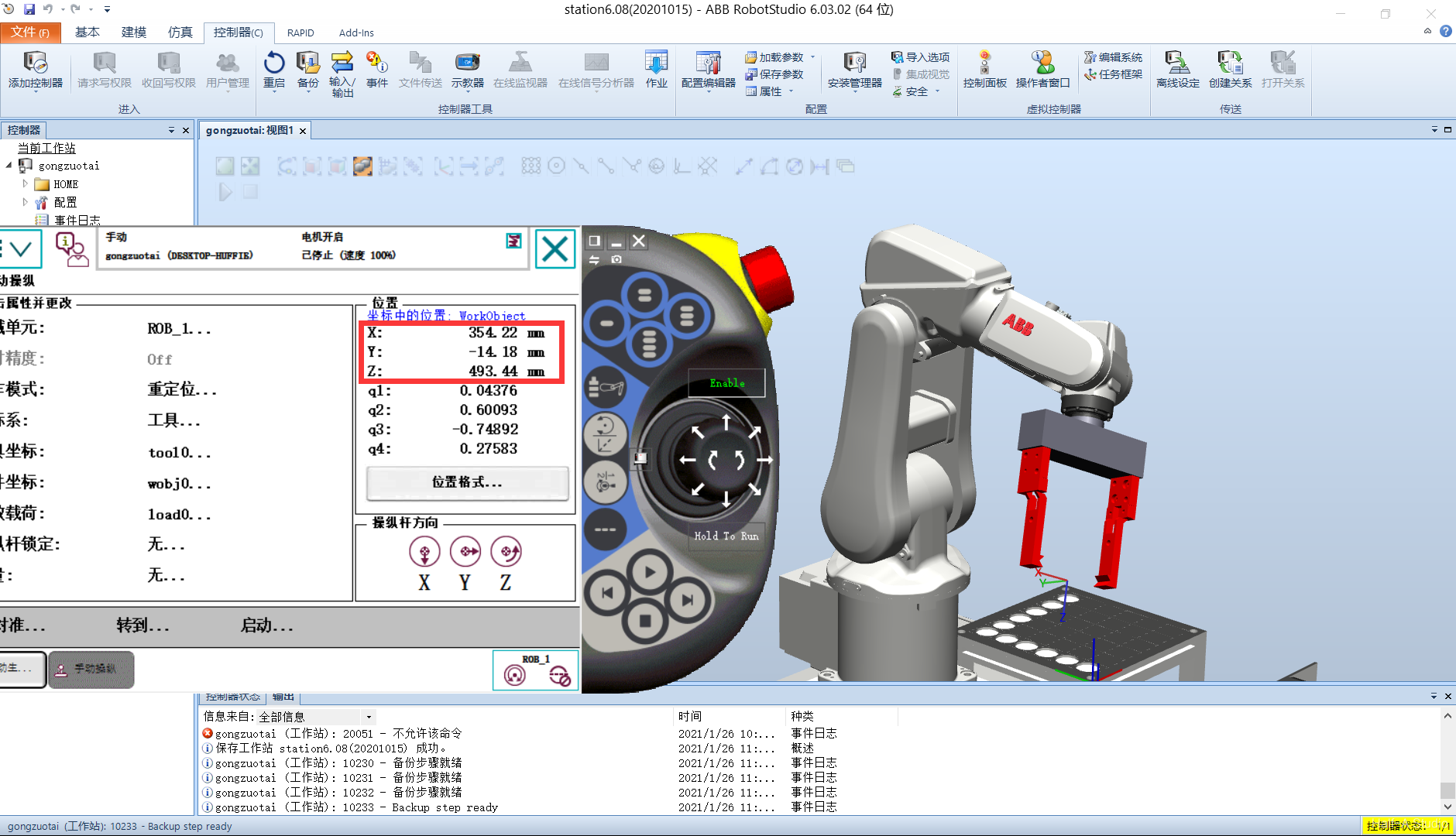
Remove the gripper and measure the coordinates at the gripper tip. Click Modeling - Measure - Point to Point, select the gripper's base and end faces, and record the resulting z-coordinate value. Reinstall the gripper on the end of the robot. Open the Virtual FlexPendant, go to Manual Operation - Tool Coordinates - New, change the name, and click Initial Value in the lower-left corner. Set the first z (coordinate position) to the measured value, 215.30; set the mass parameter mass to 1; and enter an initial estimate for the second z (center-of-gravity position). Verify the coordinates, set Motion Mode to Reorient, and set Tool Coordinates to the coordinates created above. Moving the joystick shows the robot rotating about the center point between the two gripper tips.
Open a robot system and the Virtual FlexPendant. Click Menu - Manual Operation - Motion Mode. Four motion modes are displayed below. The single-axis options are Axes 1-3, plus Axes 4-6; these are followed by linear operation and reorientation. Here, select Axes 1-3, then click OK. On the right side of the manual operation screen, you can see the robot's position information and joystick directions.
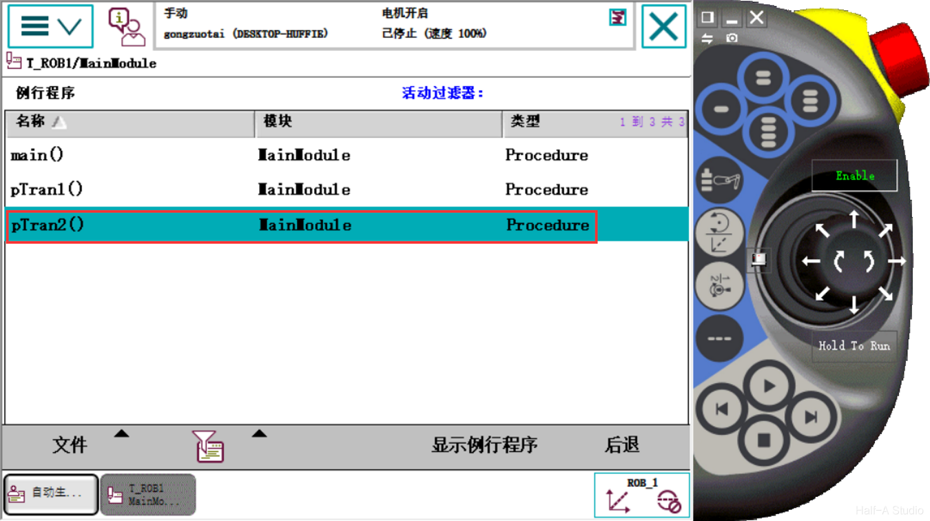
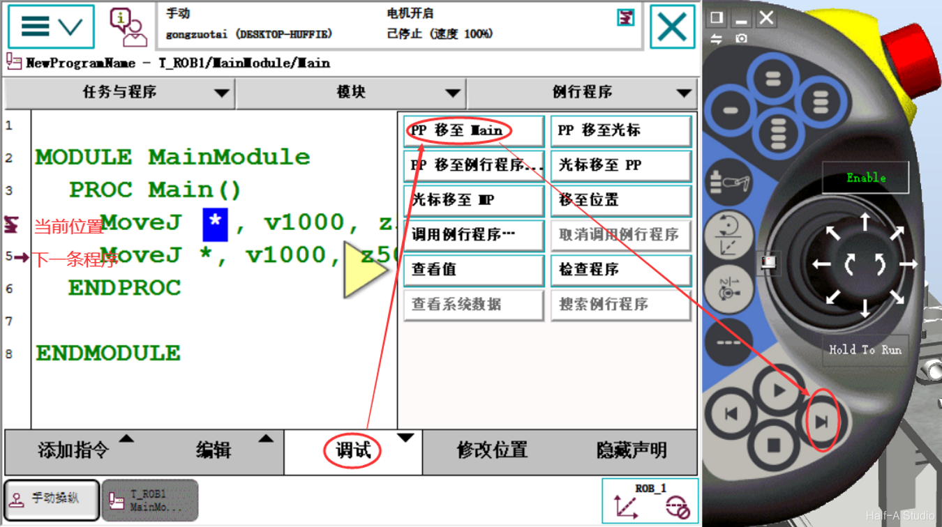
Open the main menu > Program to see the program name on the top line. T_ROB1 is a task; you can choose one task for each mechanical unit. The second level is modules, divided into system modules and program modules. Modules split the robot's required functions into separate modules—think of them like folders. The third level is routines—the programs the robot system actually executes.
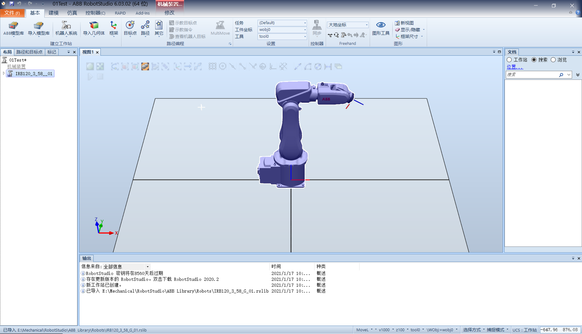
Extract the installation package, run the setup.exe program in the package, and follow the prompts to install it. The process is quite simple. After installation, double-click RobotStudio_5.61.02注册补丁.reg. Open RobotStudio to complete the installation.
In WordPress, content is mainly divided into two parts, posts and pages. WordPress plugins can add, modify, or remove functionality from a WordPress site. The Media Library is mainly used to manage attachments uploaded through WordPress, such as images, videos, and other files.
Case structures are similar to if…else… and switch structures in C and are mainly used to select among branches of program logic. A case structure contains two or more subdiagrams or cases. Only one case executes at a time. Right-click the case structure border to add, duplicate, delete, reorder, or select the default case. Multiple input/output tunnels can be created.
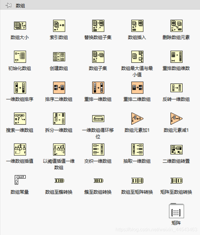
When processing a series of similar data and performing repeated calculations, consider using an Array. An Array groups data elements of the same type. Place an Array shell on the front panel and drag a data object or element into the shell to create an Array. Array functions such as Array Size, Index Array, Build Array, Array Max & Min, Sort, and Split Array can all be performed with Array functions.
Property nodes provide access to object properties. In applications that may need to programmatically change the appearance of front panel objects in response to specific inputs, these changes can be configured by editing property nodes. Right-click a control on the block diagram to create a property node. To configure multiple properties, drag the top or bottom border to add properties. A property node executes its properties from top to bottom.
The purpose of variables is to transfer data between parallel loops. Shift registers can transfer data generated by the previous iteration to the next iteration. Right-click the loop border to add a shift register. The shift register on the right stores the data at the end of each iteration, while the shift register on the left provides the stored data to the next iteration.
A While Loop executes at least once, while a For Loop can execute 0 times. A While Loop automatically outputs the value from the last iteration, while a For Loop automatically outputs an array. You can right-click the border of a While Loop and convert it to a For Loop from the shortcut menu.
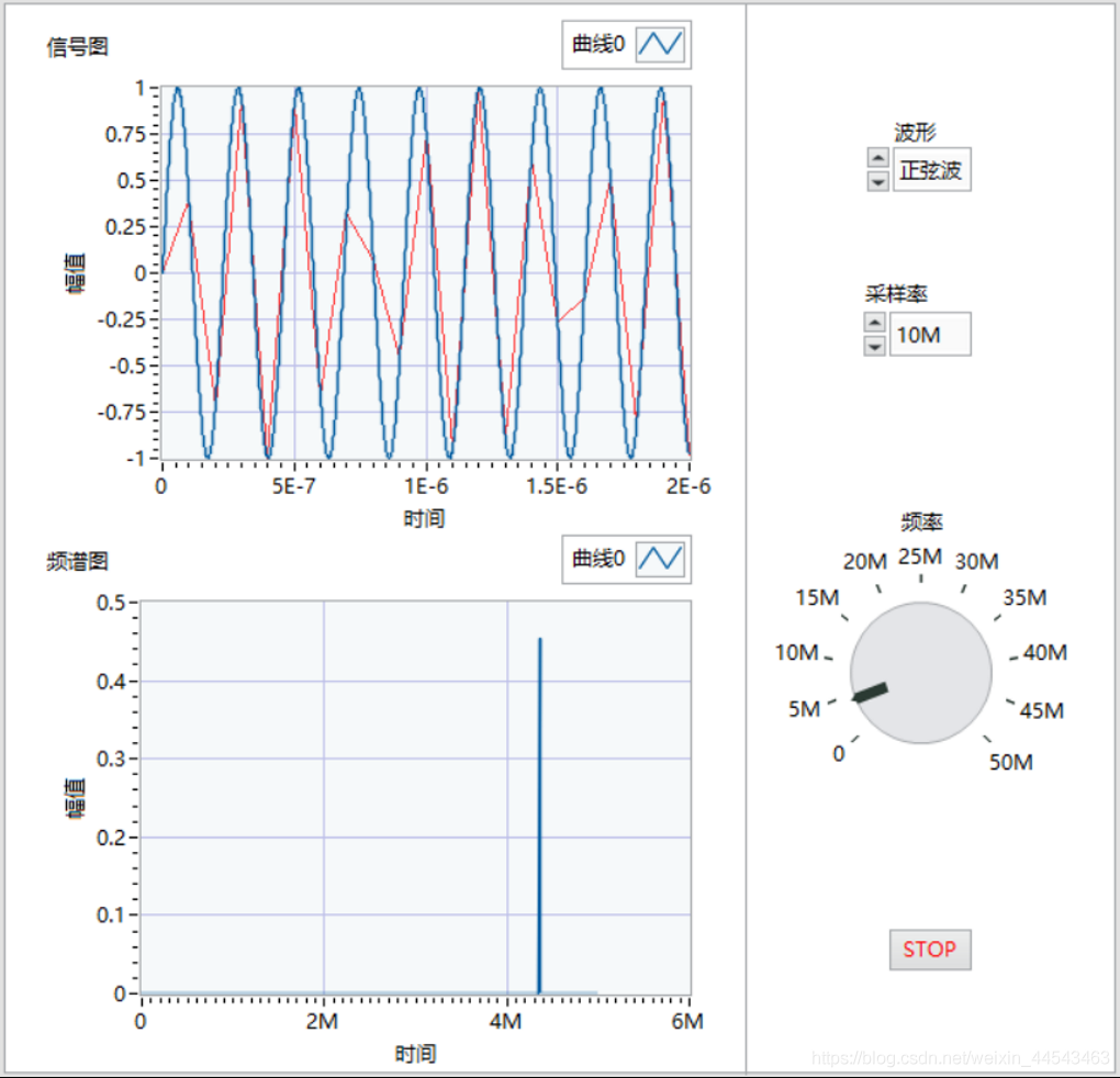
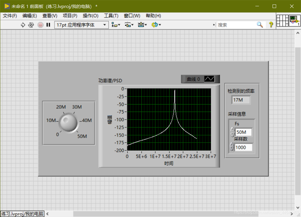
Generate a sine-wave signal with a frequency of 0-50M; choose a sampling rate of 10M/50M/100M; detect the signal frequency; output the sampled signal's power spectrum; and restart averaging if the frequency or sampling rate changes.
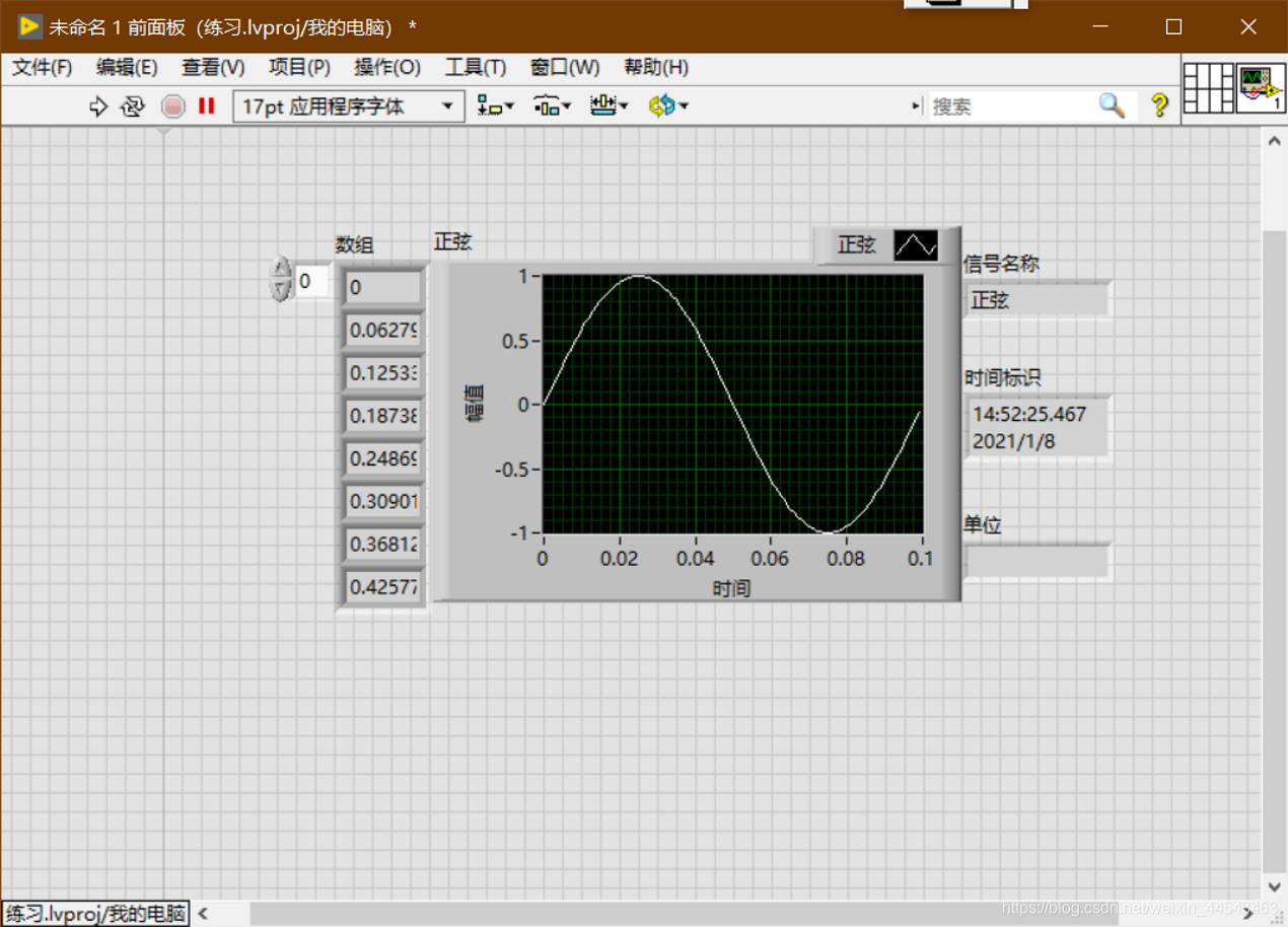
In LabVIEW, the dynamic data type is shown in dark blue. Only Express VI can produce and receive ExpressVI. Use the Get Dynamic Data ExpressVI to retrieve the properties of dynamic data, and use the Set Dynamic Data Attributes ExpressVI to set properties such as the signal name, timestamp, and time mode.
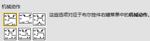
Numeric controls can represent different types of numeric values. The most important setting for Boolean controls is the mechanical action. The display type of string controls can be changed from the shortcut menu. To add items to a control's drop-down list and reorder them, right-click an enum or ring control and select Edit Items from the shortcut menu, or click the Edit Items tab in the Properties dialog box.
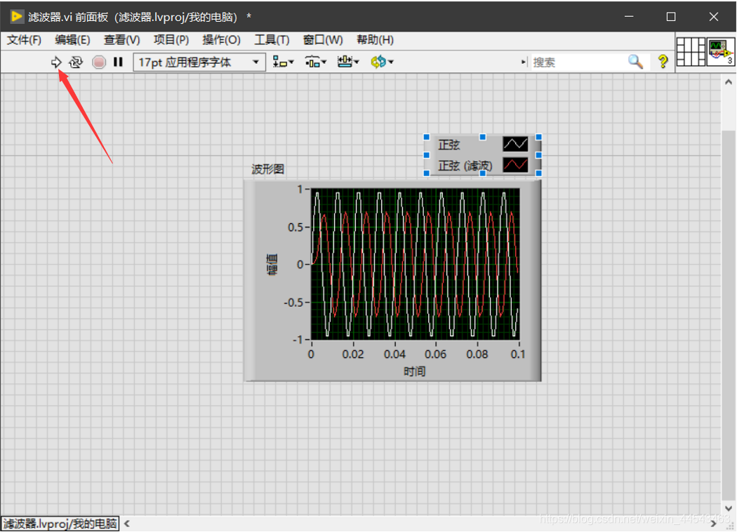
Place an Express VI on the block diagram, configure the dialog box that appears, wire the Express VI, then save and run the VI.
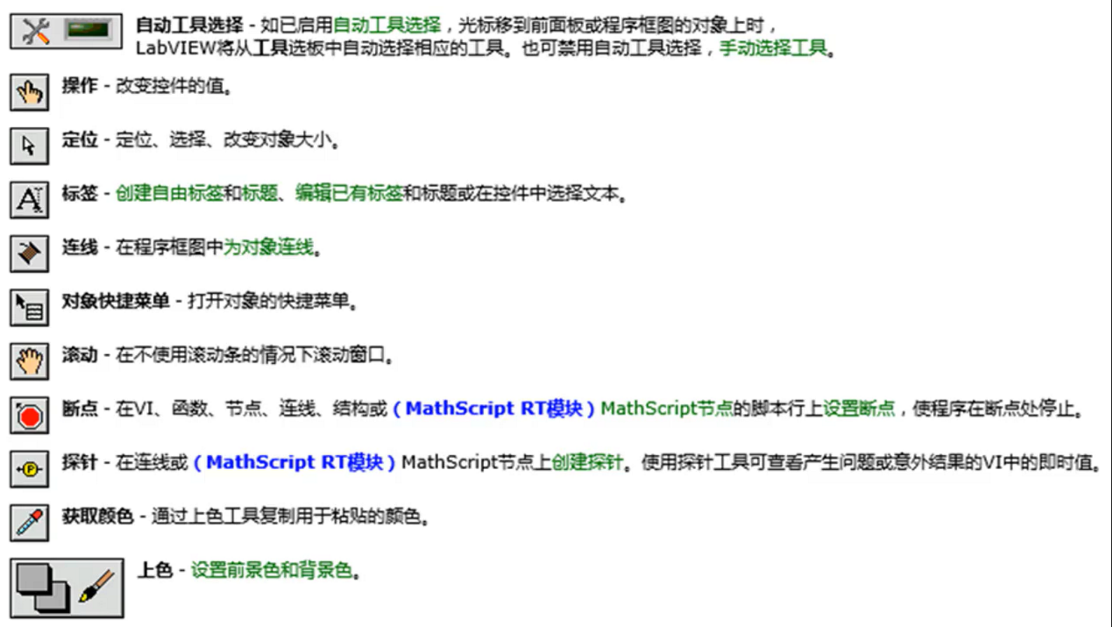
Controls come from the Controls palette. Right-click to open the Controls palette. You can add a control to the front panel by clicking it or dragging it. A block diagram consists of terminals (from the front panel), subVIs, functions, constants, structures, and wires.
Fundamentals of Digital Methods: Common Functions. 1. Cross Product 2. Vector Normalization 3. Matrix Multiplication 4. Matrix Multiplication.
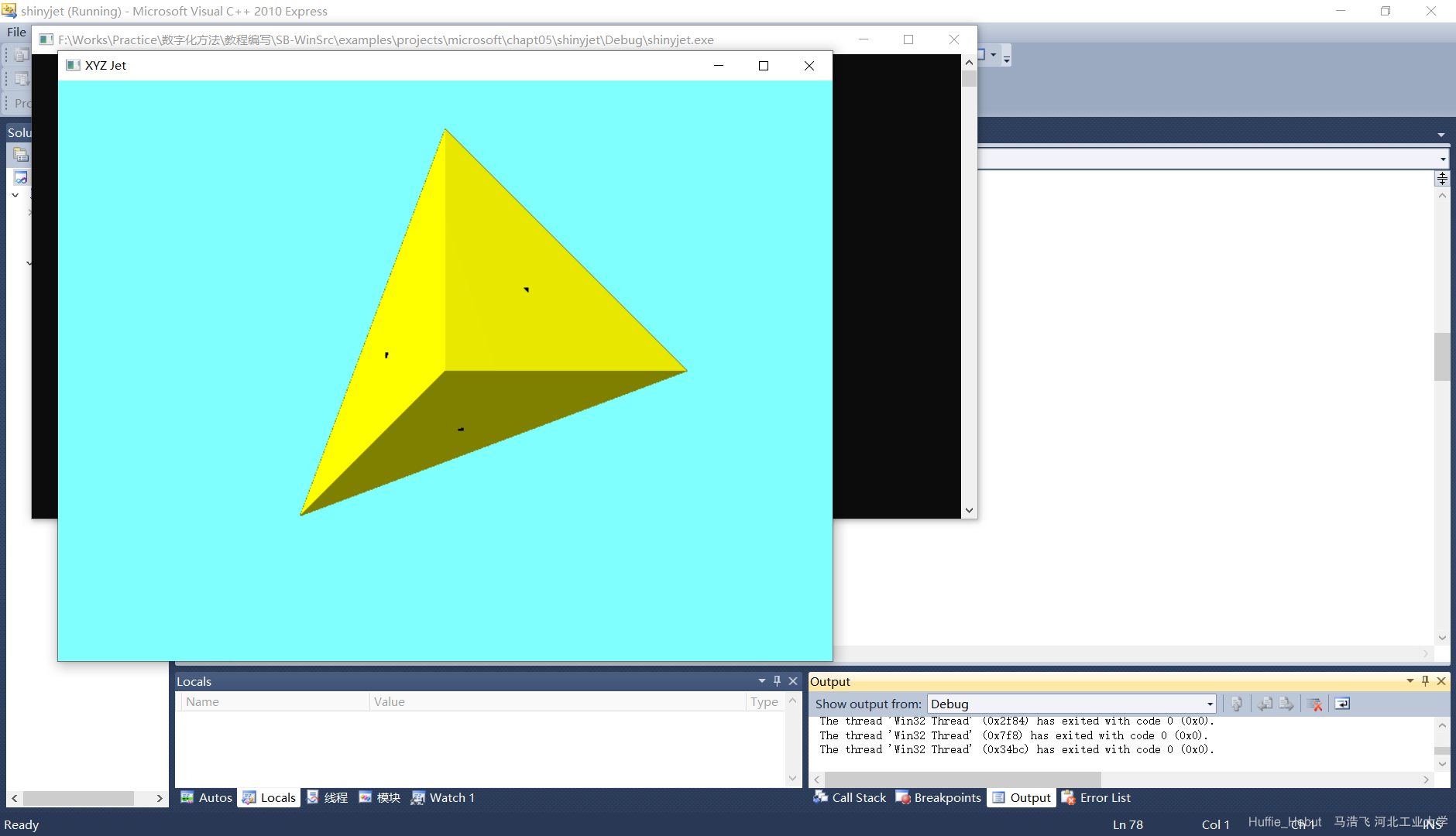
Use OpenGL to perform various basic operations, including generating a tetrahedron, importing a local model, and applying matrix operations to a model, for a better understanding of digitization methods.