Contents
We are all familiar with cameras, which can map a set of points in three-dimensional space onto a two-dimensional plane. This mapping process requires a geometric model to describe it.
The simplest and most fundamental model is the pinhole camera model, which describes the camera’s basic projection and imaging behavior.
However, the cameras we commonly use have lenses. Because of the lens, distortion occurs when light is projected and imaged, so a distortion model is needed for a more accurate description.
In many applications, cameras are also used for ranging, so this article also introduces the stereo camera model and the RGB-D depth camera model.
Pinhole Camera Model
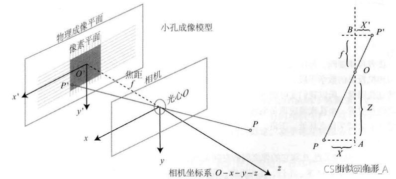
The process of converting points on a real object into pixels in an image can be summarized as follows: ① First obtain the coordinates of the actual point in the world coordinate system ② Convert the world coordinates to coordinates in the camera coordinate system ③ Map the camera coordinates to a pixel in the image
1.1 Imaging Principle
We all did the pinhole imaging experiment in middle school physics. A point in real space passes through a pinhole and projects onto a plane as an inverted image. The distance X from an actual point to the optical axis and the distance X’ from the corresponding point on the image to the center are related by a ratio that depends on the perpendicular distance from the actual point to the pinhole and the focal length.
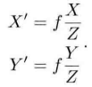
In this way, we can obtain a proportionally scaled image of the real object on the imaging plane. In a camera, however, what we ultimately obtain is individual pixels, so the formed image also needs to be sampled and quantized.
1.2 Relationship Between Physical Coordinates and Pixel Coordinates
We define a fixed pixel coordinate system ouv on the imaging plane, with origin o at the upper-left corner of the image, the u-axis parallel and in the same direction as the x-axis, and the v-axis parallel but in the opposite direction to the y-axis. The pixel coordinate system differs from physical imaging by a scaling factor and an origin translation. If the pixel coordinates are scaled by α along the u-axis and β along the v-axis, the relationship is as follows:
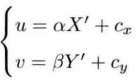
Replace X’ and Y’ in the two equations above with their expressions in terms of X and Y
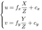
Rewriting in matrix form is more concise and intuitive
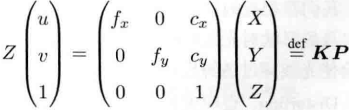
In this way, we obtain the correspondence between physical point P and pixel (u, v). The matrix formed from the intermediate quantities is called the camera intrinsic matrix K. Camera manufacturers usually provide this intrinsic matrix; if not, you need to perform camera calibration yourself.
1.3 How to Obtain Physical Coordinates
We usually describe the spatial position of a point in the world coordinate system, but in the camera model we need the position of the actual point relative to the camera. Because the camera is moving, we can derive the following expression using transformation matrices:
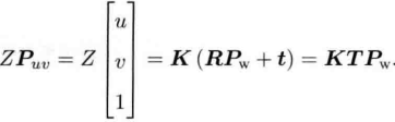
Here, the camera’s R and t are the camera extrinsics. Extrinsics change as the camera moves, while intrinsics remain unchanged.
Distortion Camera Model
2.1 Two Common Types of Distortion
To achieve better imaging quality, real cameras usually place a lens in front of the sensor. The lens affects how light propagates—that is, straight lines in the real world become curves in the image. This is called radial distortion. Radial distortion is further divided into barrel distortion and pincushion distortion.
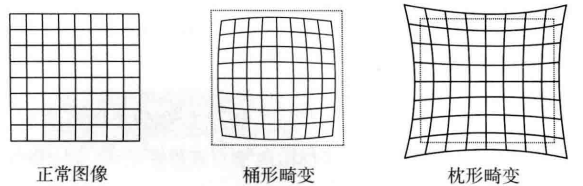
Due to mounting errors, the lens and the imaging plane are not completely parallel, which also shifts the projection position. This is called tangential distortion.
2.2 Undistortion Methods
① Radial distortion Radial distortion can be viewed as a change along the radial direction—that is, the distance from the coordinate point to the origin changes. The commonly used model is as follows, assuming distortion follows a polynomial relationship and using three parameters k1, k2, and k3 to express it.
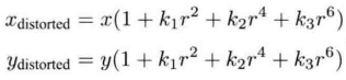
where [, ] are the normalized coordinates of the distorted point. r denotes the distance from point p to the origin of the coordinate system. ② Tangential distortion Tangential distortion can be viewed as a change along the tangential direction—that is, the horizontal angle changes. Tangential distortion is usually expressed with two parameters p1 and p2, as shown in the formula below.
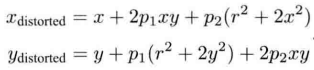
③ Combined method Combining the radial and tangential distortion formulas above, we obtain a combined undistortion formula. In other words, five distortion coefficients are sufficient to determine the correct position of a point on the pixel plane.

2.3 Example Program
#include <opencv2/opencv.hpp>
#include <string>

using namespace std;
using namespace cv;

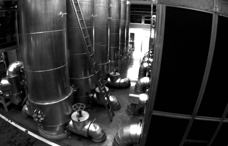
string image_file = "./distorted.png";

int main(int argc, char **argv){
		//定义畸变系数
        double k1 = -0.28340811, k2 = 0.07395907, p1 = 0.00019359, p2 = 1.76187114e-05;
        //相机内参
        double fx = 458.654, fy = 457.296, cx = 367.215, cy = 248.375;

		//读入图像,灰度图
        Mat image = imread(image_file, 0);
        Mat image_undistort = Mat(image.rows, image.cols, CV_8UC1);

        //遍历每个像素,计算后去畸变
        for (int v = 0; v < image.rows; v++){
                for (int u = 0; u < image.cols; u++){
                		//根据公式计算去畸变图像上点(u, v)对应在畸变图像的坐标(u_distorted, v(distorted)),建立对应关系
                        double x = (u - cx) / fx;
                        double y = (v - cy) / fx;
                        double r = sqrt(x * x + y * y);
                        double x_distorted = x*(1+k1*r*r+k2*r*r*r*r)+2*p1*x*y+p2*(r*r+2*x*x);
                        double y_distorted = y*(1+k1*r*r+k2*r*r*r*r)+2*p2*x*y+p1*(r*r+2*x*x);
                        double u_distorted = fx * x_distorted + cx;
                        double v_distorted = fy * y_distorted + cy;

						//将畸变图像上点的坐标,赋值到去畸变图像中(最近邻插值)
                        if (u_distorted >= 0 && v_distorted >=0 && u_distorted < image.rows && v_distorted < image.cols){
                                image_undistort.at<uchar>(v, u) = image.at<uchar>((int)v_distorted, (int)u_distorted);
                        }else{
                                image_undistort.at<uchar>(v, u) = 0;
                        }
                }
        }
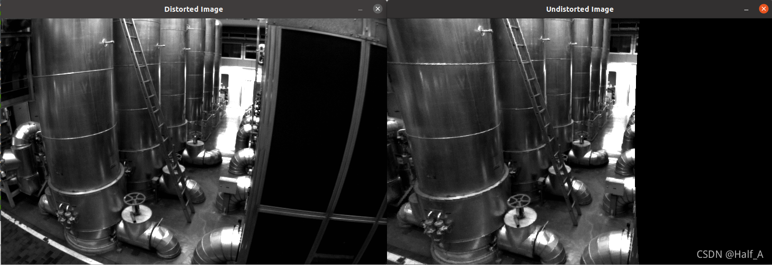
        imshow("Distorted Image", image);
        imshow("Undistorted Image", image_undistort);
        waitKey();
        return 0;
}
Comments