Contents
SLAM Notes Column: https://blog.csdn.net/weixin_44543463/category_10925276.html
I. Rotation Matrix
1.1 Vectors
A vector and its coordinates are two different concepts. A vector is simply a quantity with magnitude and direction. Only after a coordinate frame in three-dimensional space is specified can we talk about the coordinates of a vector in that frame. Therefore, a vector’s coordinates depend both on the vector itself and on the choice of coordinate frame. The inner product of vectors describes their projection relationship.

The cross product of two vectors is perpendicular to both, with magnitude |a||b|sin<a,b>.

1.2 Euclidean Transformation
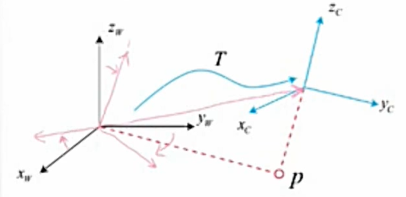
The rotation and translation between two coordinate frames are collectively called the transformation between frames. While a robot moves, we often define an inertial frame (the world frame), which can be treated as fixed. The robot itself is a moving frame. If we need to know how a vector converts between the robot frame and the world frame, we first obtain the vector’s coordinates in the robot frame, then transform them into the world frame according to the robot’s pose. This conversion is described by a matrix T. Robot motion is rigid-body motion: the length and angles of the same vector do not change across frames. This kind of change is a Euclidean transformation.
(1) Rotation matrix Suppose a unit orthonormal basis (,,) undergoes a rotation and becomes (,,). For the same vector (which does not move with the rotating frame), we have
In matrix form:

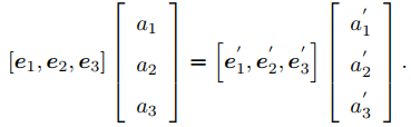
To express the transformation between the two coordinate representations, multiply both sides of the equation by [ ]T. The matrix on the left becomes the identity:
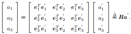
The middle matrix—an orthogonal matrix with determinant 1—is the so-called rotation matrix. Meanwhile, the inverse of this rotation matrix describes the opposite rotation.

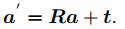
(2) Translation matrix The translation matrix is very simple: simply add the translation to the coordinates after rotation.
1.3 Transformation Matrix
When transforming in the form below, repeated changes often become overly complex and no longer satisfy a linear relationship.

Therefore we usually use homogeneous coordinates and a transformation matrix as follows. Append a one to the end of a three-dimensional vector to make a four-dimensional vector, called the homogeneous coordinates . Put the rotation matrix and the translation into the same matrix; this matrix T is called the transformation matrix.
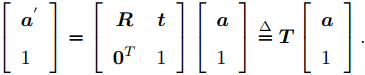
With homogeneous coordinates, multiple transformation matrices can be multiplied in sequence to obtain a single overall transformation matrix, accumulating multiple transforms.

II. Axis-Angle and Euler Angles
2.1 Motivation
A rotation matrix has nine entries, but a rotation has only three degrees of freedom. A transformation matrix uses sixteen entries to express a six-DoF transform, so the representation can be redundant. At the same time, a rotation matrix must be orthogonal, and a transformation matrix likewise needs constraints. In some cases these constraints make solving difficult.
2.2 Axis-Angle
(1) Definition Any rotation can be characterized by a rotation axis and a rotation angle. We can use a vector whose direction coincides with the rotation axis and whose length equals the rotation angle; such a vector is called a rotation vector or axis-angle. With the axis-angle representation, only a three-dimensional vector is needed to describe a rotation. Likewise, for a transformation matrix, we can express it with one axis-angle and one translation vector. (2) Conversion between axis-angle and rotation matrix Suppose there is a rotation with axis and angle θ. Clearly the rotation vector is θ. Converting from axis-angle to a rotation matrix can use the Rodrigues formula:

We can also compute the conversion from a rotation matrix to axis-angle. (Because vectors along the rotation axis are unchanged after rotation, the rotation axis is the eigenvector of the rotation matrix corresponding to eigenvalue 1.)

2.3 Euler Angles
Neither the rotation matrix nor axis-angle is very intuitive, whereas Euler angles are easier for humans to understand. (But they are uncommon in programs.) Euler decomposed a rotation into three successive rotations about different axes. For example, rotating in Z-Y-X order yields yaw-pitch-roll angles.
- Rotate about the body’s Z axis to obtain the yaw angle;
- Rotate about the Y axis after that rotation to obtain the pitch angle;
- Rotate about the X axis after that rotation to obtain the roll angle.
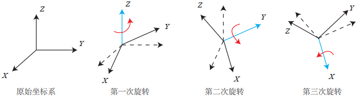
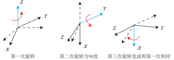
Euler angles suffer from gimbal lock. For example, in ZYX order, after the first rotation about Z and a second rotation of 90° about Y, the x-axis coincides with the system’s original Z axis, so the third rotation and the first are about the same axis, and one degree of freedom is lost. Therefore programs rarely use Euler angles to represent a robot’s pose.
III. Quaternions
3.1 Introduction
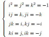
A quaternion is an extended form of complex numbers. We know that complex numbers can represent rotation in the complex plane: multiplying by i means a 90 degrees counterclockwise rotation in that plane, and a complex number on the unit circle can express two-dimensional planar rotation. A quaternion has three imaginary parts and can express rotation in three-dimensional space.


Multiplication of the imaginary parts of a quaternion is analogous to multiplying by the imaginary unit i, with a corresponding relationship that closely resembles the cross product in three-dimensional space.
3.2 Quaternion Operations
| Operation | Formula |
|---|---|
| Addition/subtraction |  |
| Multiplication | 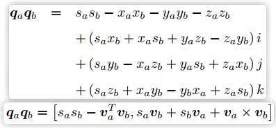 |
| Conjugate |  |
| Norm |  |
| Inverse | 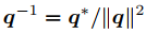 |
| Scalar multiplication | 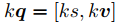 |
| Dot product |  |
3.3 Representing Rotation with Quaternions
(1) Conversion among quaternions, axis-angle, and rotation matrices
| Conversion | Formula |
|---|---|
| Axis-angle to quaternion: | 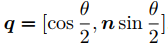 |
| Quaternion to axis-angle | 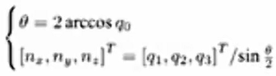 |
| Quaternion to rotation matrix | 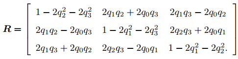 |
(2) Using a quaternion to represent rotation
A quaternion has three imaginary parts i, j, k. Taking the three coordinate values as coefficients of the three imaginary parts and setting the real part to zero converts a three-dimensional spatial coordinate into a pure imaginary quaternion.
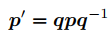
Use a quaternion to represent the rotation.

Rotation of a spatial point can be expressed by quaternion multiplication. The rotated point is as follows
Reference: Gao Xiang — Fourteen Lectures on Visual SLAM Related GitHub: https://github.com/gaoxiang12/slambook
Comments