Multi-Machine ROS Topic Communication
Two Ubuntu systems (such as a desktop PC and a robot), connected via Ethernet cable, sharing ROS nodes.
105 posts
Two Ubuntu systems (such as a desktop PC and a robot), connected via Ethernet cable, sharing ROS nodes.
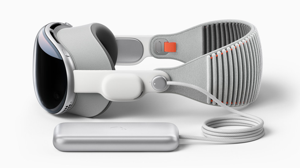
This article documents the complete process for setting up an Apple Vision Pro development environment, covering physical-device debugging with Xcode, Unity + PolySpatial configuration, Play to Device streaming, app packaging, and basic concepts such as visionOS space types and Volume Camera.
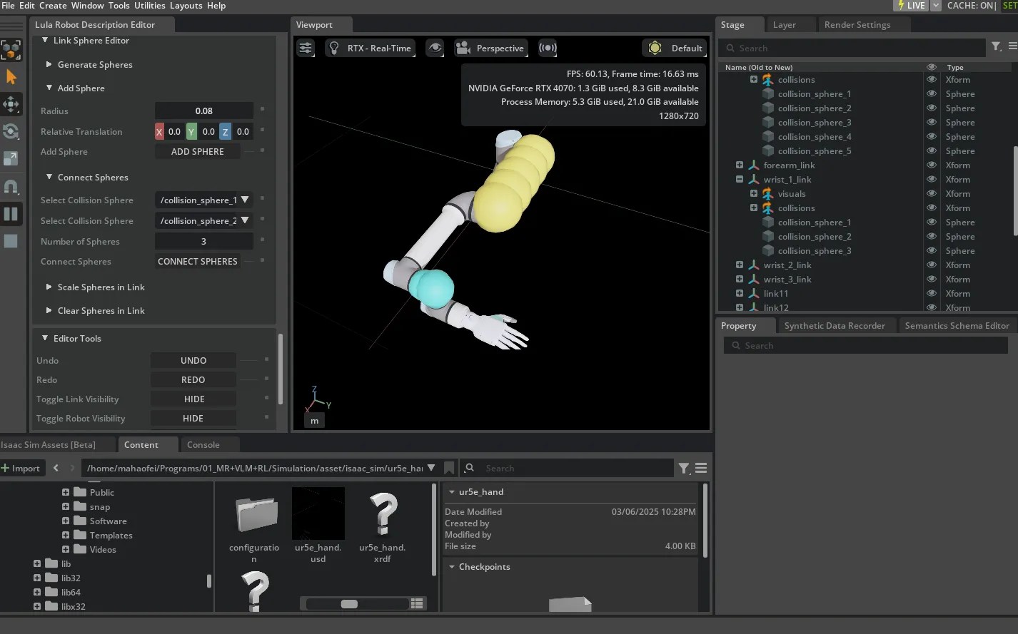
Methods for implementing Cartesian-space control (inverse kinematics) in Isaac Sim.
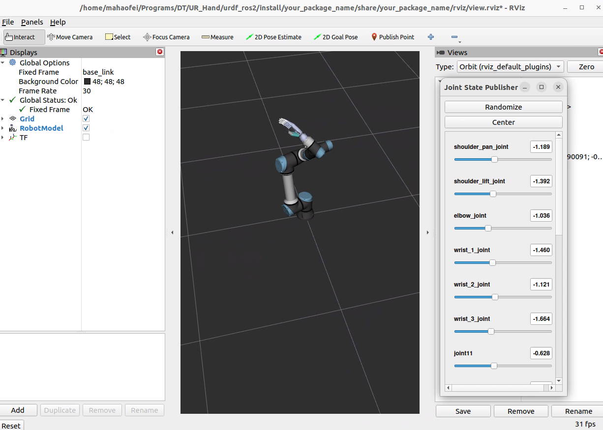
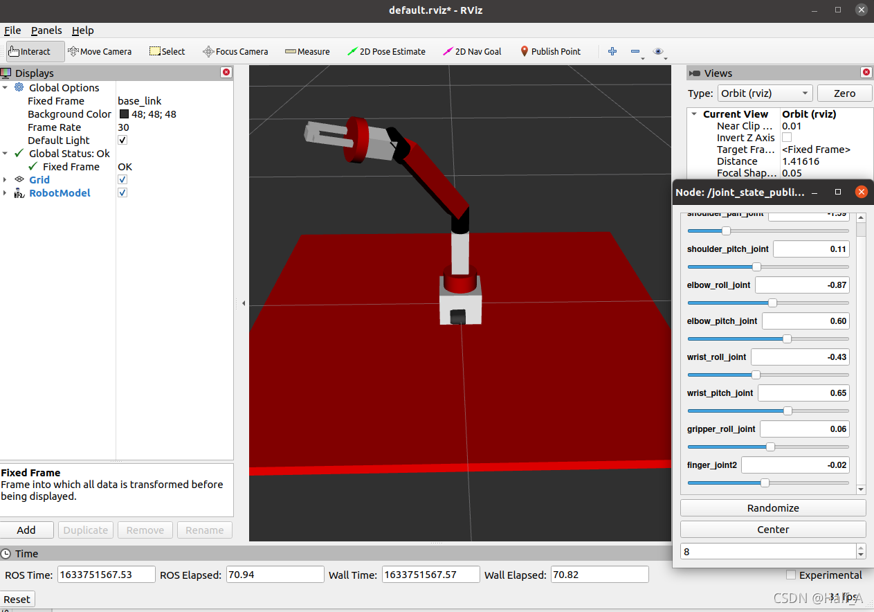
Visualize URDF files with ROS2 and Rviz2, with an example package and a complete modification tutorial.
I recently installed version 22.04 of Ubuntu and ROS 2 Humble on a new computer. To keep up with the times, I learned the new ROS 2 commands and summarized them here for easy reference.
An introduction to the NVIDIA Isaac Sim simulation environment, covering installation, the GUI, and basic usage of Python programs.
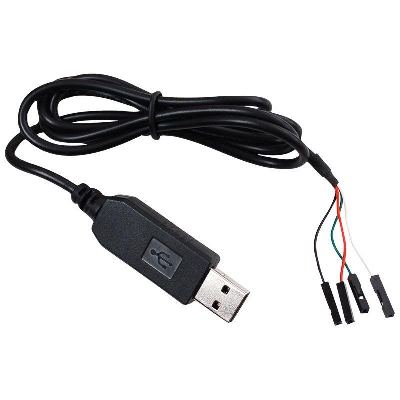
Assign stable, custom device names (such as /dev/gripper) to USB-to-serial devices on Ubuntu
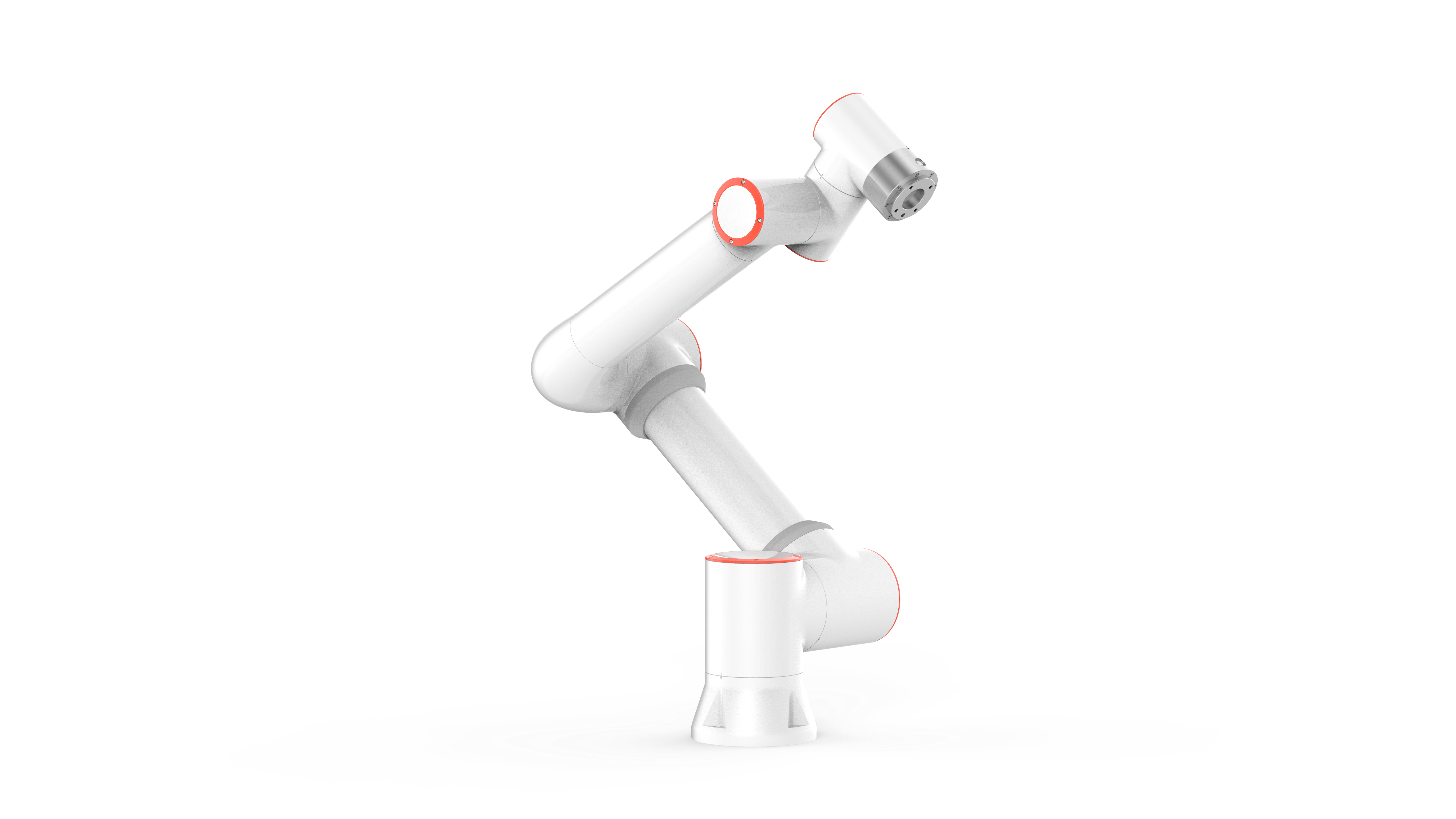
The FR5 is a 6-DoF robotic arm with a configuration similar to the UR5. This article introduces basic motion control with its Python SDK.
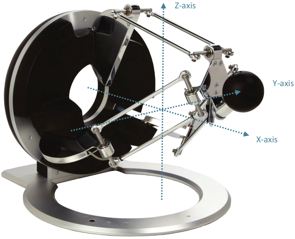
Configuration and basic program usage for the Omega.7 virtual haptic force-feedback master device
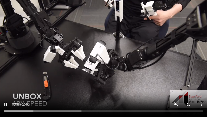
A Stanford University bimanual imitation learning system with a full hardware and software stack that enables fine manipulation on low-cost, imprecise hardware.
robomimic is a framework for robot learning from demonstrations. The project provides a range of demonstration data for robot manipulation and offline learning algorithms, enabling standardized testing of tasks and algorithms.
A lecture from Stanford CS25 V2 on robot learning, presented by a Google Brain engineer.
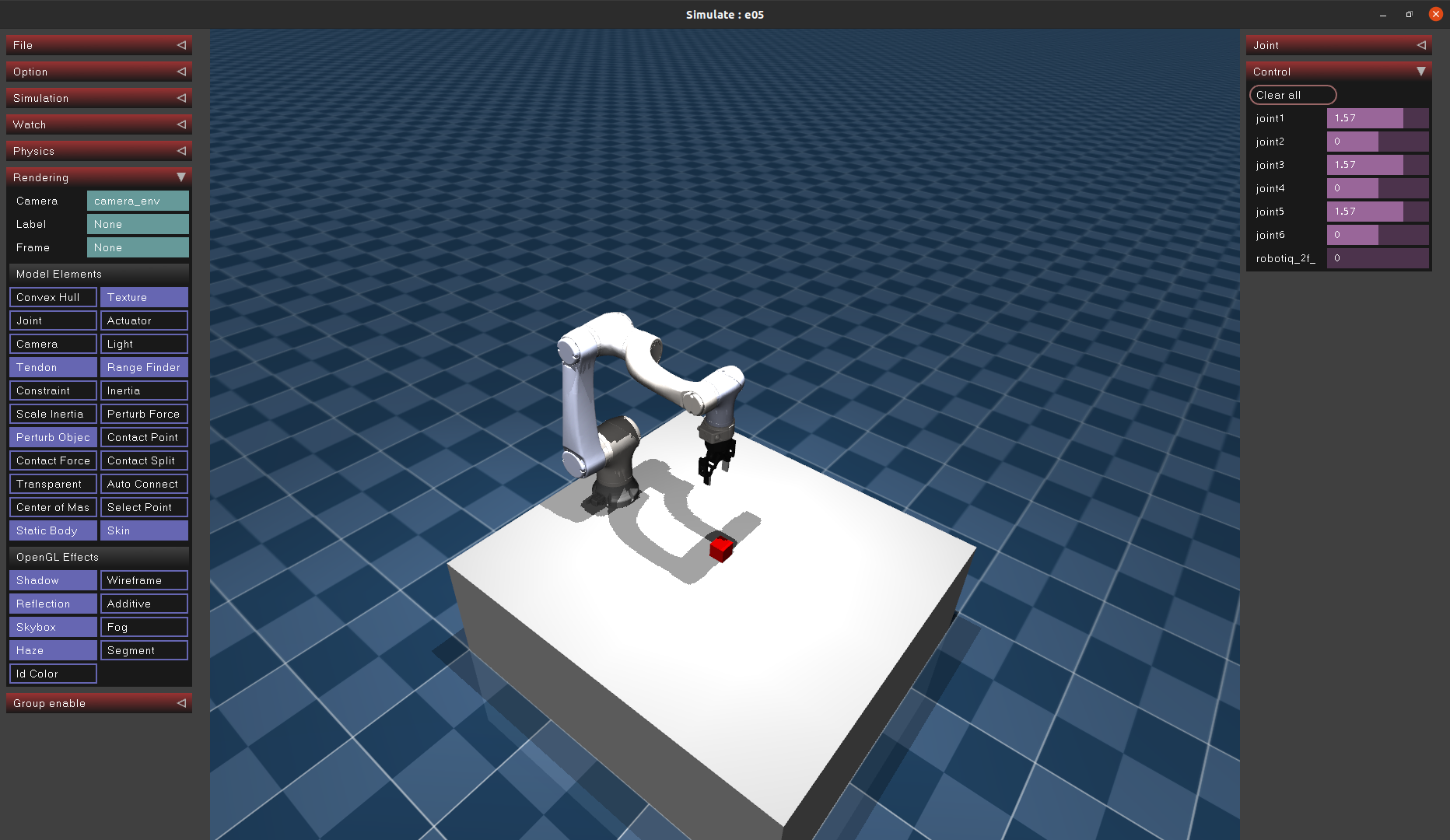
Import a custom robot model into MuJoCo to lay the groundwork for building simulation environments for future reinforcement learning.
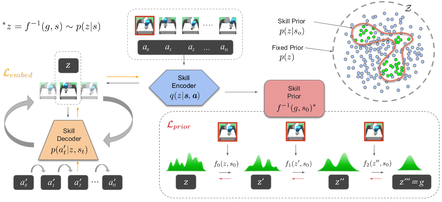
A skill-unit-based reinforcement learning method that decomposes tasks into skills, establishes mappings between skills and states, and learns a skill-selection policy
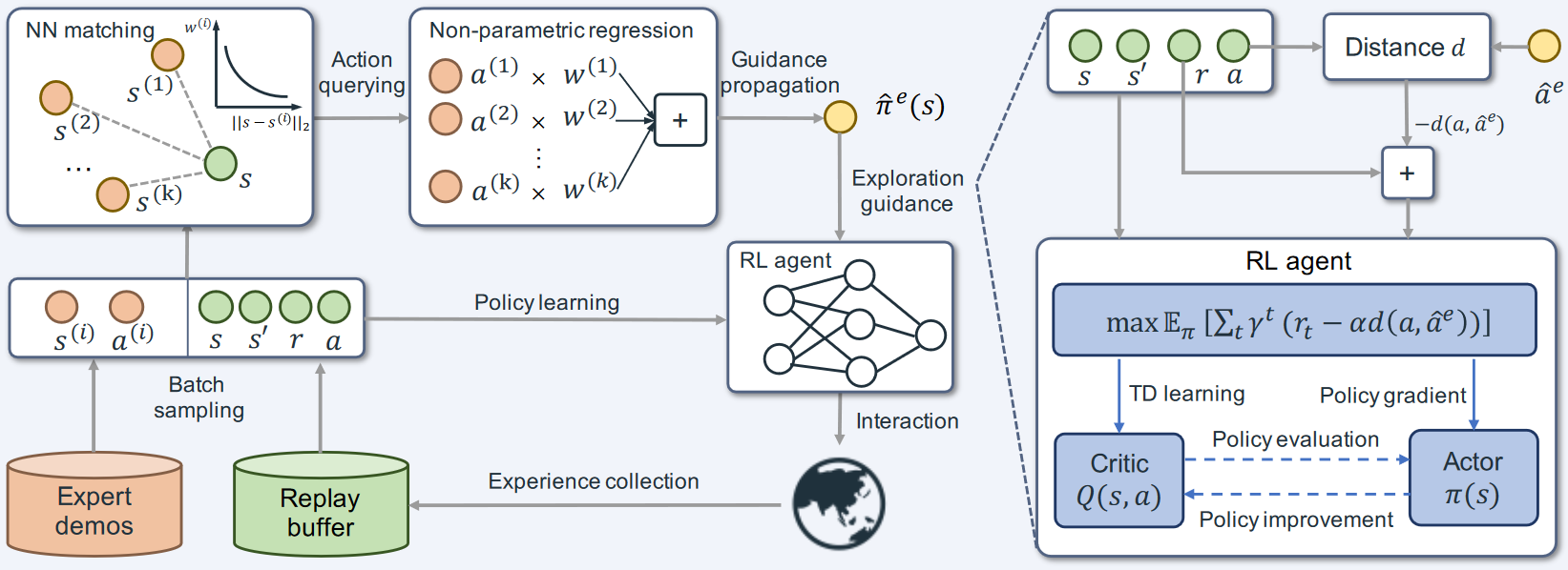
A surgical robot reinforcement learning method based on an improved DDPG+BC approach, developed by Yun-Hui Liu's team at The Chinese University of Hong Kong
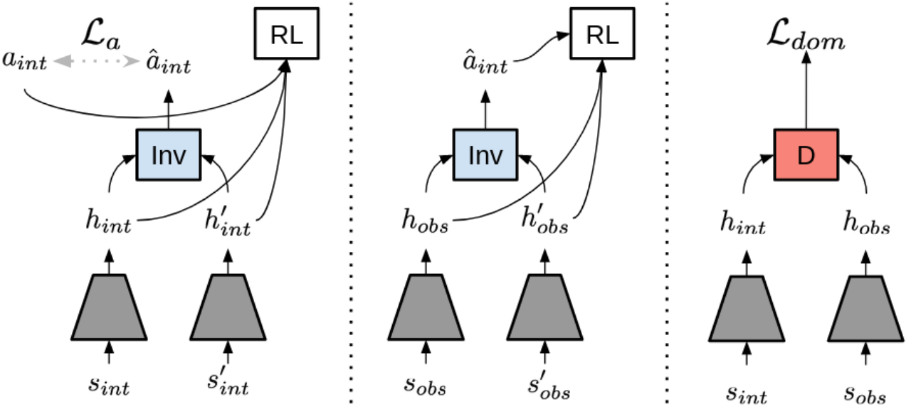
Survey and notes on reinforcement learning-based robot motion imitation methods.
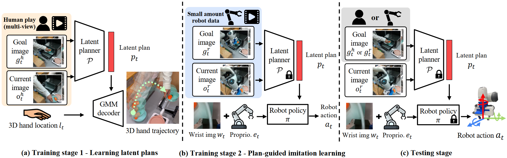
A long-horizon imitation learning method from Fei-Fei Li's team at Stanford University that learns by watching human actions.
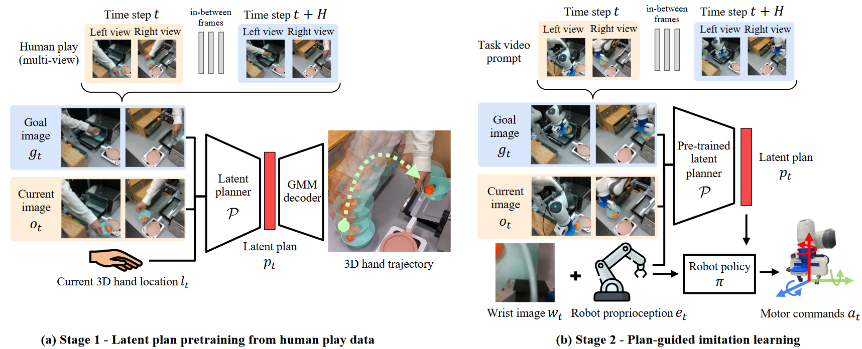
A survey of research on methods for robot motion generation and planning learned from videos of humans grasping objects.
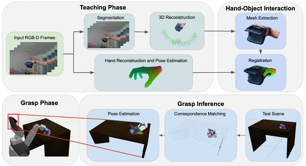
A survey of research on robotic grasping learned from videos of humans grasping objects.
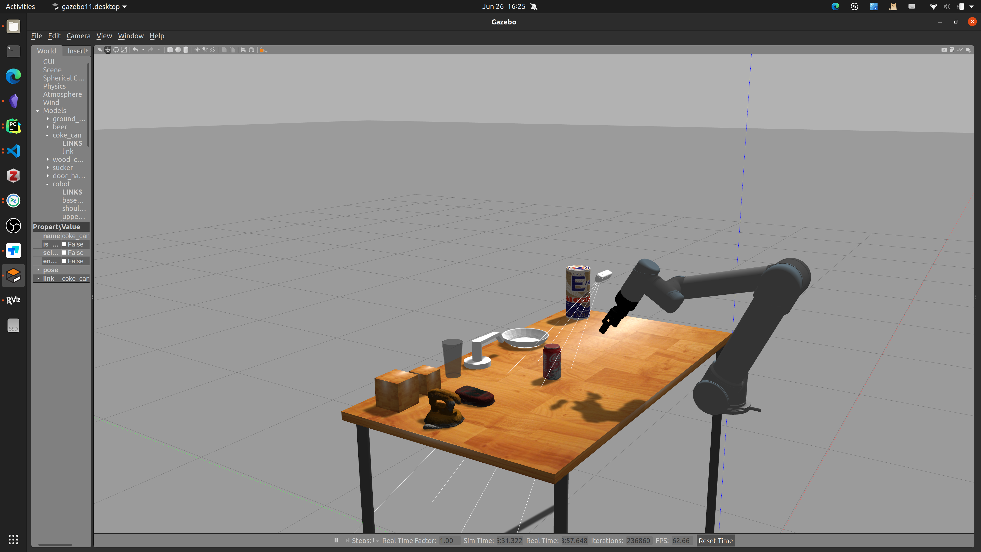
Build a 6D robotic arm simulation environment in Gazebo, add a camera, and implement a grasping simulation experiment.
A collection of various error messages encountered while using the ROS system for robot experiments, updated irregularly.
Reproducing the RGB Matters algorithm proposed by Shanghai Jiao Tong University.
A survey of grasp pose estimation papers from top conferences and journals over the past three years
Reproducing Contact GraspNet, a grasp estimation algorithm proposed by NVIDIA
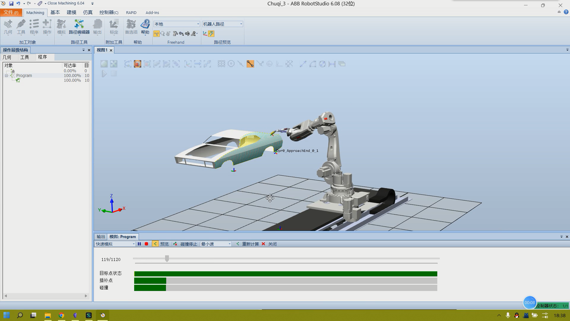
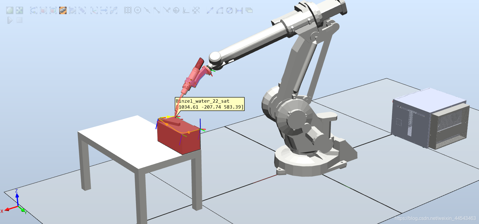
Import a CAD model with complex curved surfaces, such as a car body, into RobotStudio. Use RobotStudio for path planning to enable a robotic arm to paint the car body.
Implemented bidirectional serial communication over UART between a host PC running ROS Noetic and an STM32F1 development board.
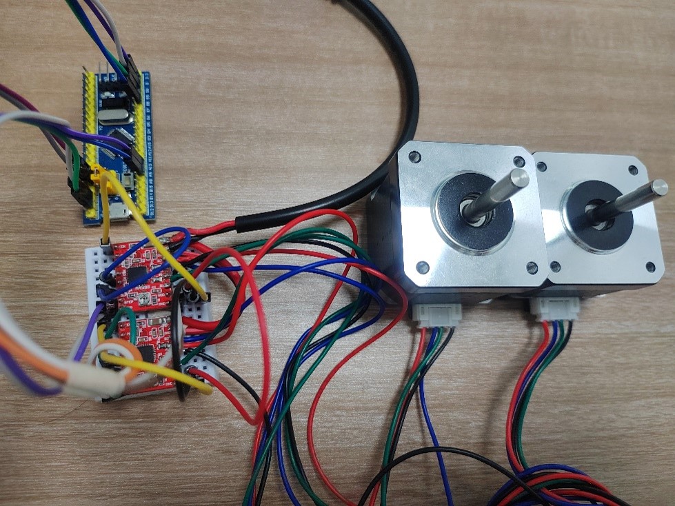
Driving a 42-series stepper motor with an A4988 chip, tested on the STM32F1 platform, with up to 16× microstepping.
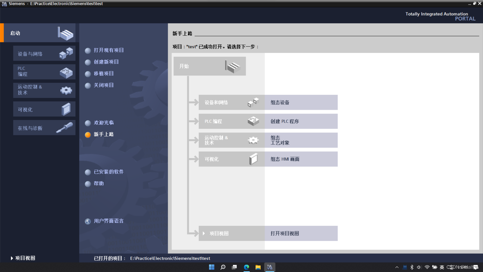
An installation guide for Siemens TIA Portal V15 PLC automation design software.
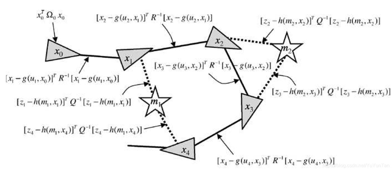
g2o (General Graph Optimization) is a graph optimization library that combines nonlinear optimization with graph theory. We can use g2o to solve any least-squares problem that can be represented as graph optimization.
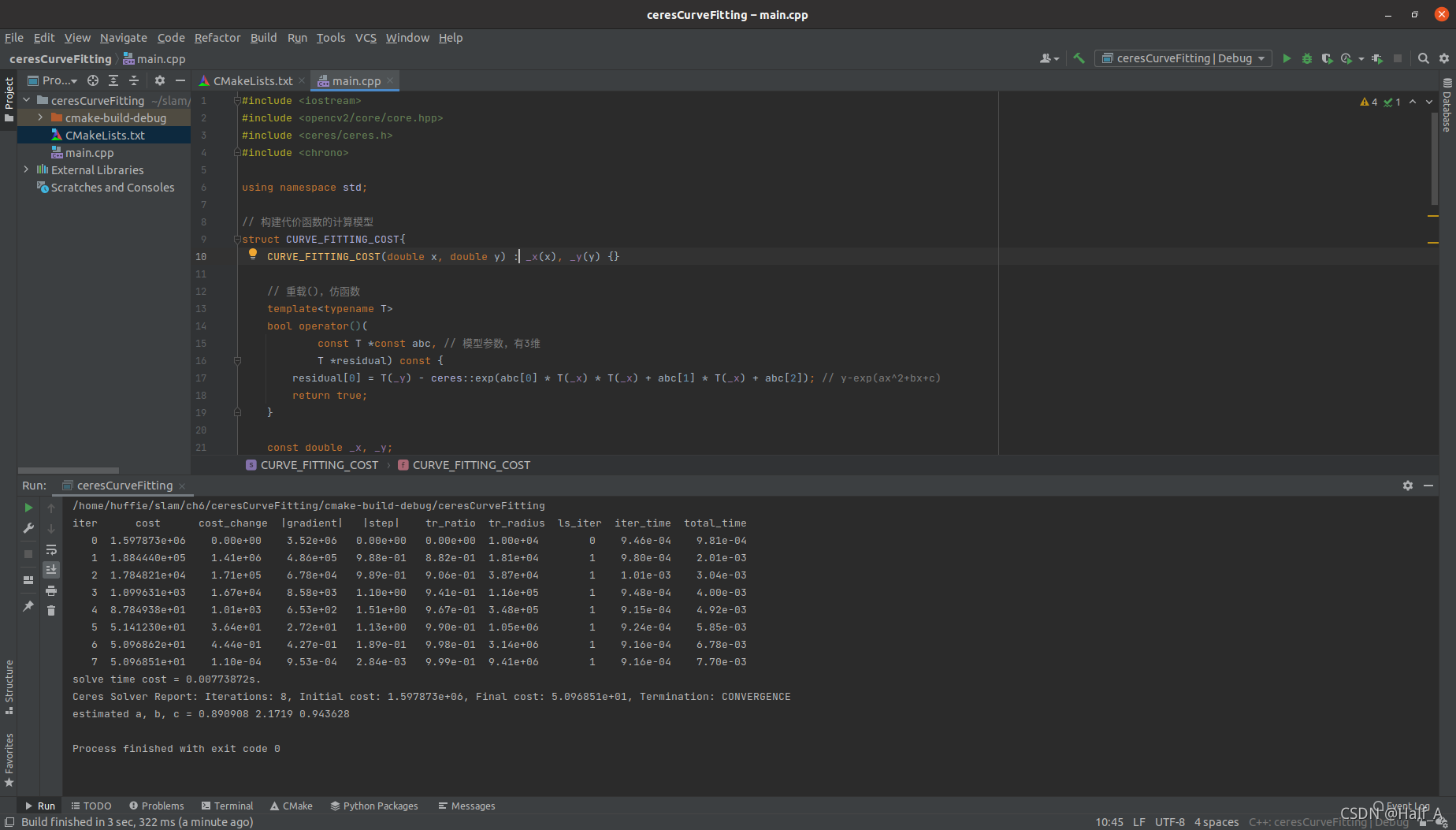
Ceres is a library for solving least-squares problems. We only need to define the problem to be optimized and let it perform the computation. Usage: 1. Define each parameter block. A parameter block is simply a vector, but it can also have a special structure such as a quaternion or Lie algebra……
I was using an STM32F103C8T6 minimum system board. After debugging the STM32 program on Windows and successfully establishing serial communication, the serial connection stopped responding after I restarted the computer.
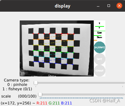
The purpose of camera calibration is to eliminate camera distortion. For details on how distortion occurs, see the previous article. The process of calibrating a USB camera in ROS can be broadly divided into several steps. ① Install the usb_camera driver package; ② run usb_cam to capture images from the USB camera; ③ download and print a checkerboard, then calibrate the camera.
This tutorial explains how to download and install the Keil5 51 edition. Keil5 is a very user-friendly and powerful C language software development system. Keil5 provides a clear and intuitive interface, is very easy and convenient to use, and includes compiler, compiler, installer package, and debugging and tracing features.
This tutorial explains how to download and install the MDK edition of Keil5. Keil5 is a very user-friendly and powerful C software development system. Keil5 provides a clear, intuitive interface, is very easy and convenient to use, and includes a compiler, compiler, installation package, and debugging and tracing features.
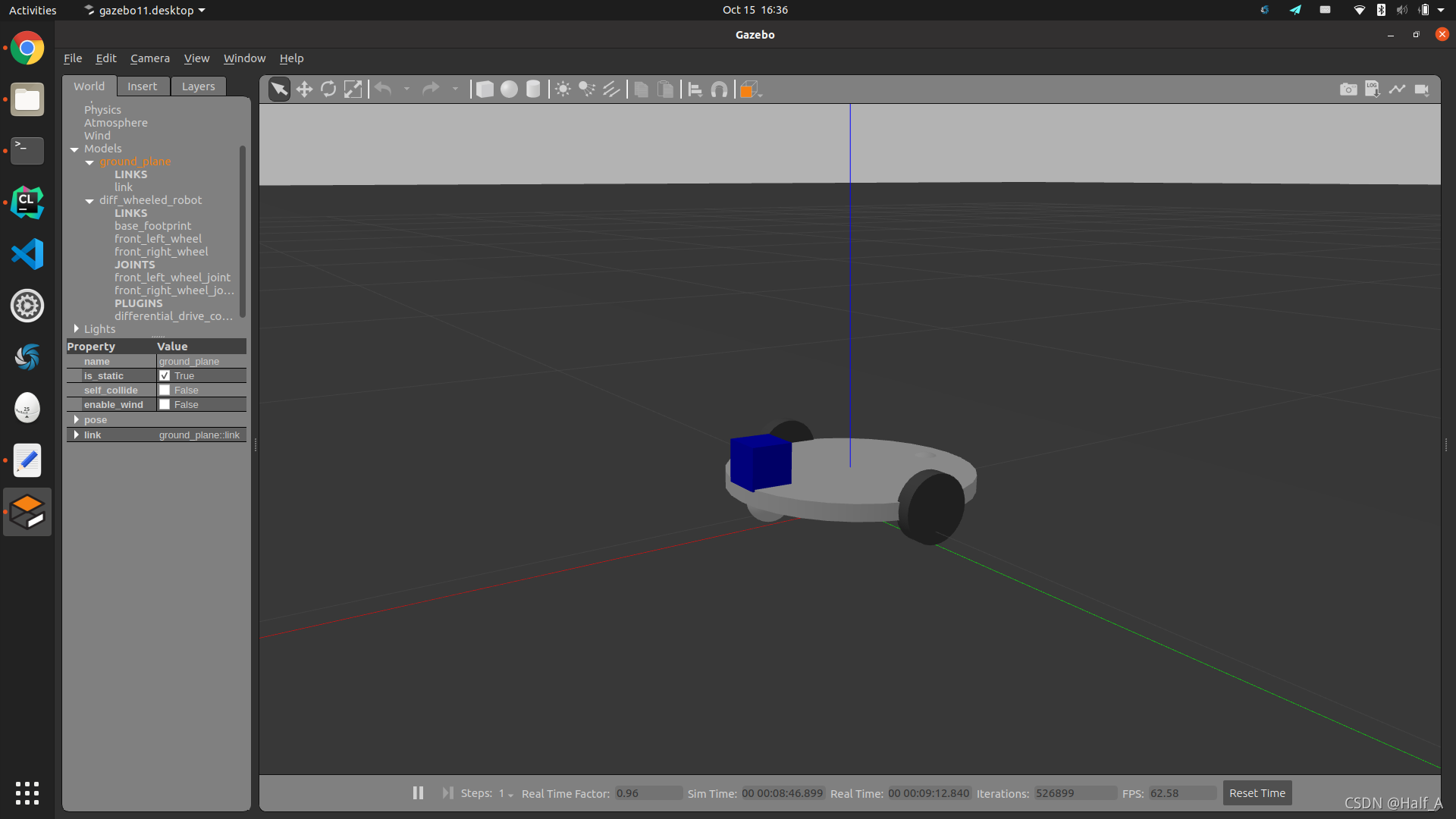
Use xacro description files to create a differential-drive robot model, simulate the model in Gazebo, then use the libgazebo_ros_diff_drive.so plugin to control the robot's motion, and finally implement keyboard control of the robot in the Gazebo environment.
LabVIEW 2020 Chinese edition installation tutorial with Aliyun Drive links and detailed installation steps. For learning reference only—do not use for commercial purposes!
Why create a three-dimensional robot model? Robot simulation tools can help us identify critical errors in a design. Model simulation means that we create a robot model, so it does not necessarily look exactly like the real robot. However, because it is a simulation, the model must include all the characteristics of the real hardware.
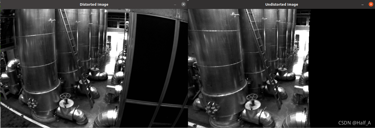
This article first introduces the imaging principle of pinhole cameras and the conversion between physical coordinates and pixel coordinates. It then introduces a distortion model based on real-world camera issues, presents undistortion formulas, and includes a detailed example program.
Starting with the creation of a workspace and package, this article explains the creation and compilation steps and provides a detailed summary of commonly used ROS commands. It then uses specific examples to explain in detail how to create nodes, services, launch files, and dynamic parameters, and demonstrates how they are used.
The state machine is the most commonly used design model in engineering applications. With a state machine, we can easily implement decisions and branches in a program flowchart. A LabVIEW state machine consists of a While Loop, a Case Structure, and a shift register.
State machines are the most widely used design pattern in engineering applications. With a state machine, we can easily implement decisions and branches from program flowcharts. A LabVIEW state machine consists of a While loop, a case structure, and a shift register.
An important concept in programming is modularity, which means dividing a program into several blocks so that modifying one block does not affect the others. In LabVIEW, we use subVIs to implement modular programming.
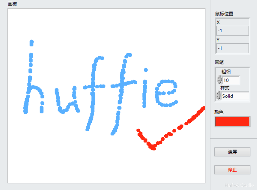
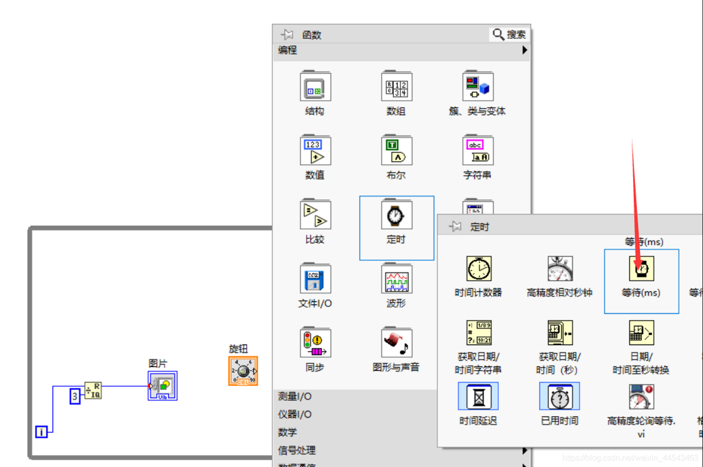
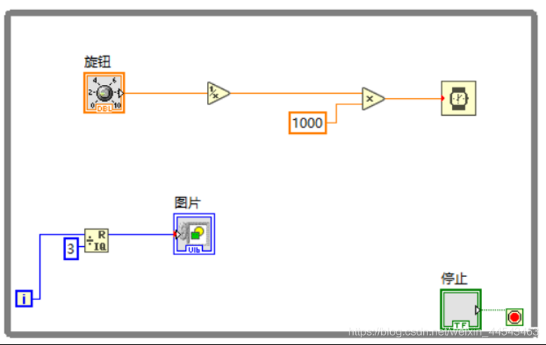
The two-dimensional Picture control provides pixel-level control and can create almost any graphical object. To display an image in a two-dimensional Picture control, you must write an image to the control programmatically. You can draw with the Picture Functions VIs.
A shift register passes the value generated in the previous loop iteration to the next iteration. Shift registers appear as pairs of terminals located at corresponding positions on the borders on opposite sides of a loop. A shift register must be initialized; that is, you must set the value that it passes to the first loop iteration.
Eigen is an open-source C++ linear algebra library that provides fast matrix and linear algebra operations, equation solving, and other features. Many higher-level software libraries also use Eigen for matrix operations. Eigen is a header-only library, so to use it, you only need to include its header files; no library linking is required.
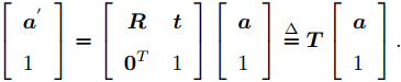
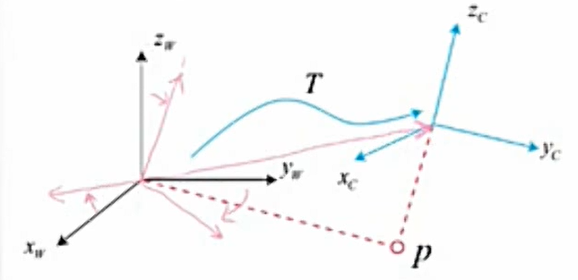
The rotation and translation between two coordinate frames are collectively called the transformation between frames. While a robot moves, we often define an inertial frame (the world frame), which can be treated as fixed. The robot itself is a moving frame.
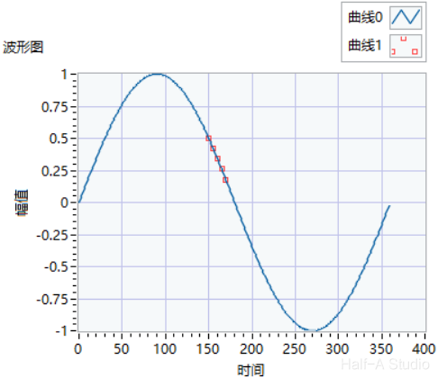
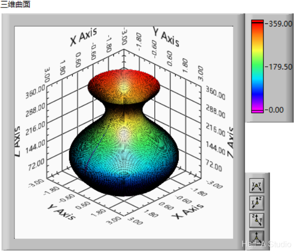
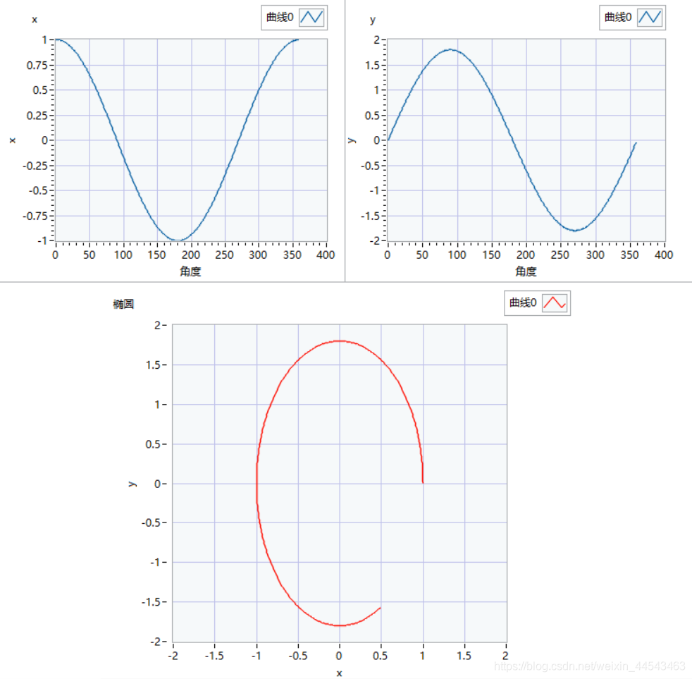
Generating a surface of revolution such as a vase essentially involves sweeping a profile along a guide curve. For a vase, the method is to sweep a circle along a curve. The circle is generated as follows: the total number of loop iterations is 360, corresponding to 360 degrees, while i represents each angle from 0~360.
A for loop runs for a fixed number of iterations and also has a conditional terminal that can terminate a while loop early, equivalent to the break statement in C. For loops are closely tied to array operations, and their most important function is processing array data.
The components used include a simulated power supply, a transformer, a bridge rectifier, a non-polarized capacitor, an electrolytic capacitor, and a three-terminal voltage regulator IC. The wiring method is shown in the figure.
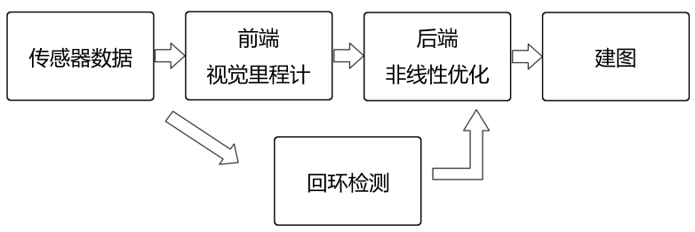
For a mobile robot, we often need it to know two things—where it is (localization) and what the surrounding environment looks like (mapping).
Rviz is a three-dimensional visualization tool that is highly compatible with robot platforms based on the ROS software framework. Rviz can graphically display robot sensor data, robot motion status, environmental information, and more.
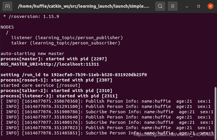
The functions of a laubch file are as follows: it configures and starts multiple nodes through an XML file. It can also start ROS Master automatically (so there is no need to run roscore separately).
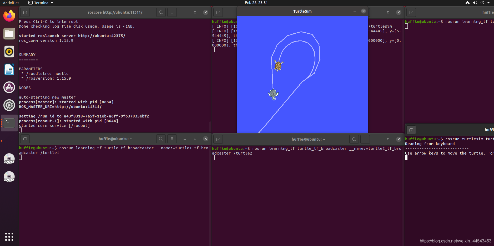
The TF package manages all coordinate frames. It keeps a ten-second history of the relationships among all frames and can show where a grasped object is relative to the robot's center frame.
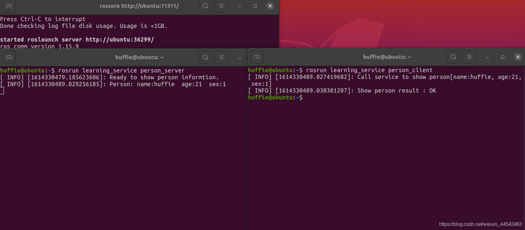
Each time the Client makes one Request, the Server sends data once. The data format is personal information such as name, gender, and so on.
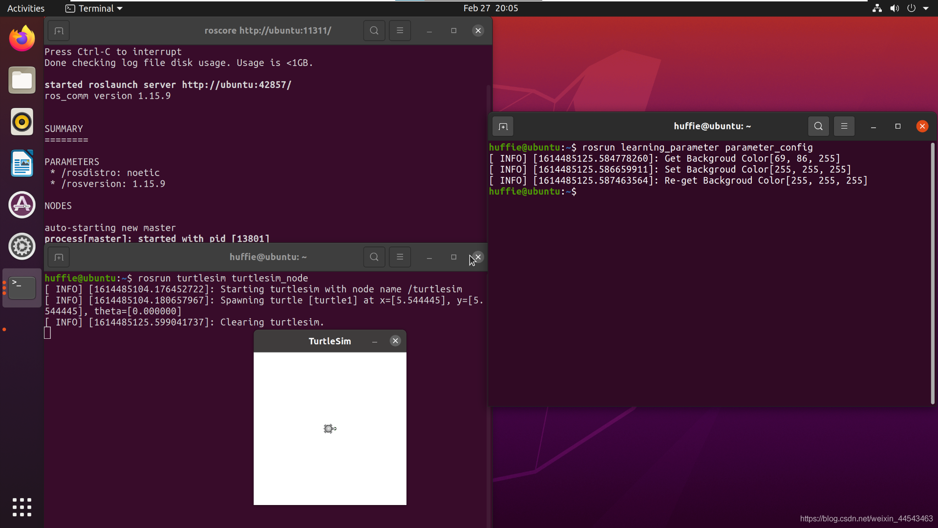
ROS Master includes a Parameter Server, which is a global dictionary that stores configuration parameters. These configuration parameters are globally accessible to all nodes.
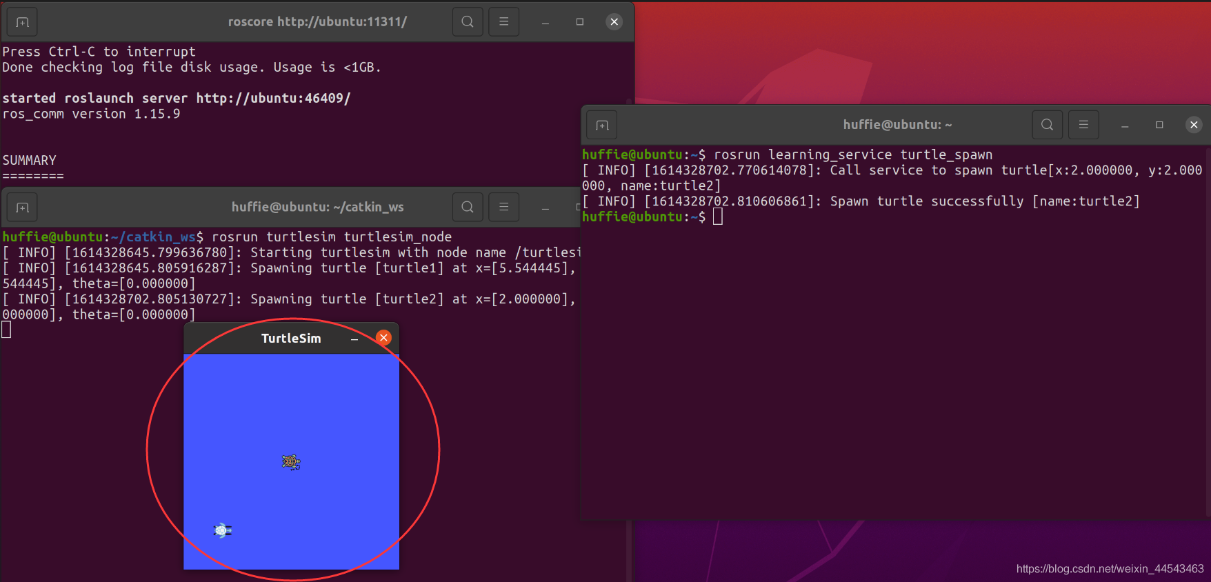
Send a service request programmatically. In other words, the client sends a request to the server to spawn a turtle, and the server returns the response to the client. Go back to the catkin_ws/src directory and create a package named learning_service.
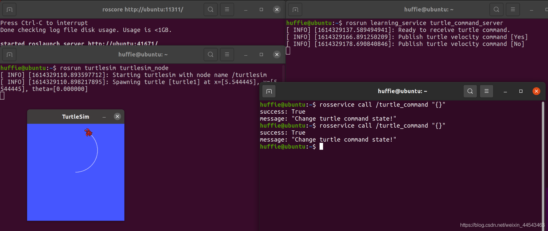
The server waits for a signal. Each time it receives a signal from the client, it toggles the turtle's motion state (moving → stopped, stopped → moving).
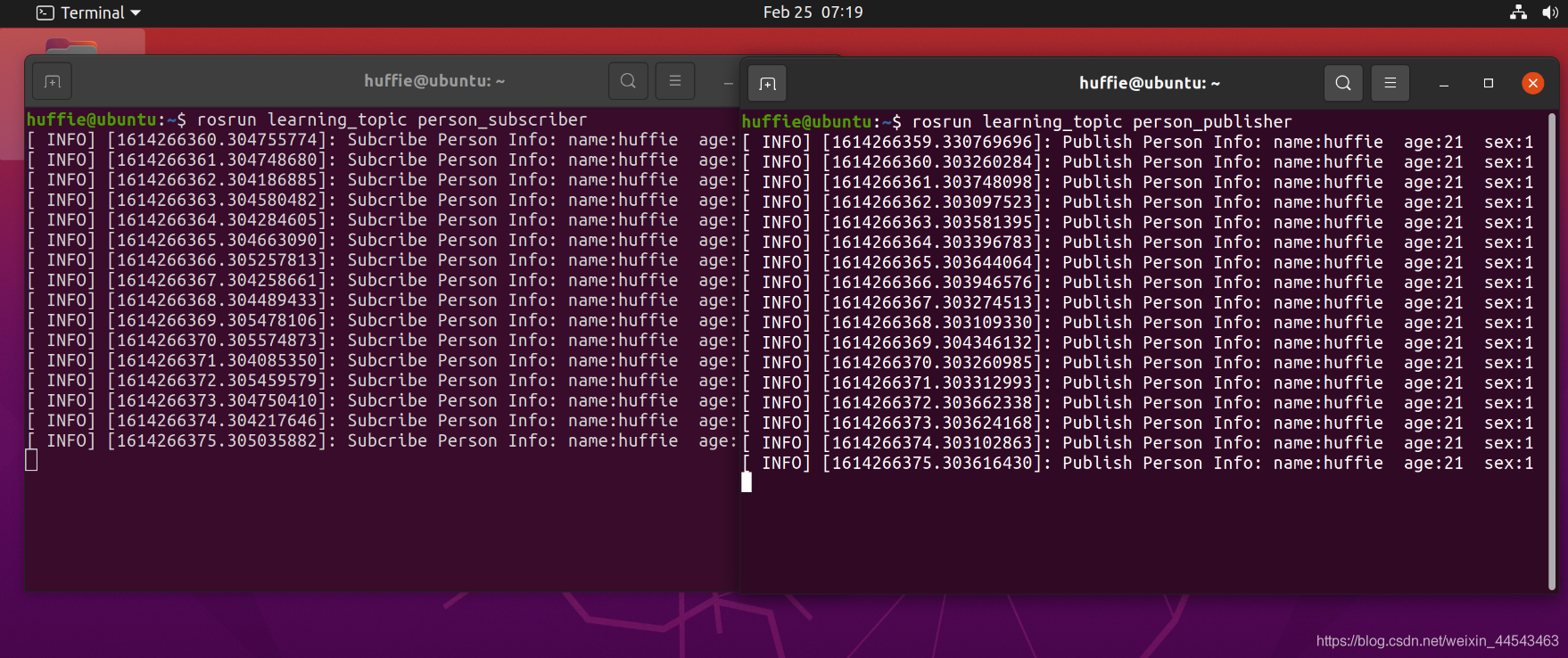
In ROS Master, you can publish and subscribe to predefined messages, such as information about a turtle's motion and pose. However, sometimes you need to define custom message types. The main objective of this section is to define a Person message containing personal information, publish it through a Publisher, and subscribe to it through a Subscriber.
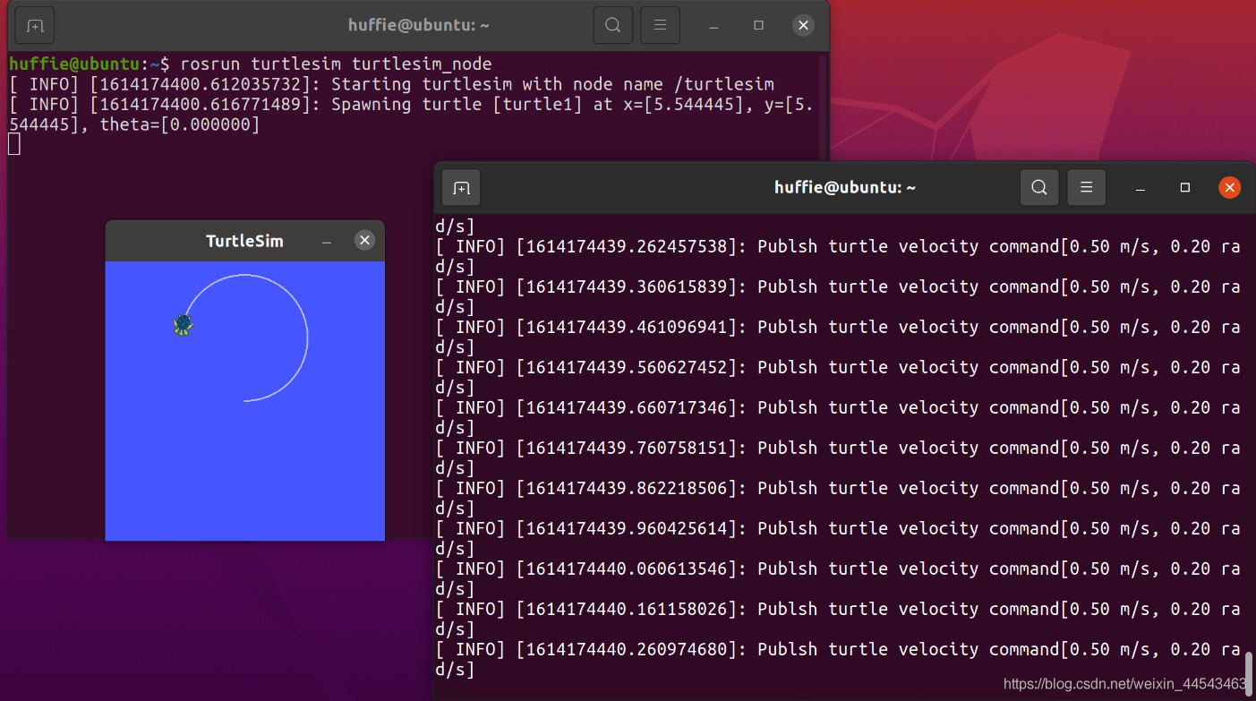
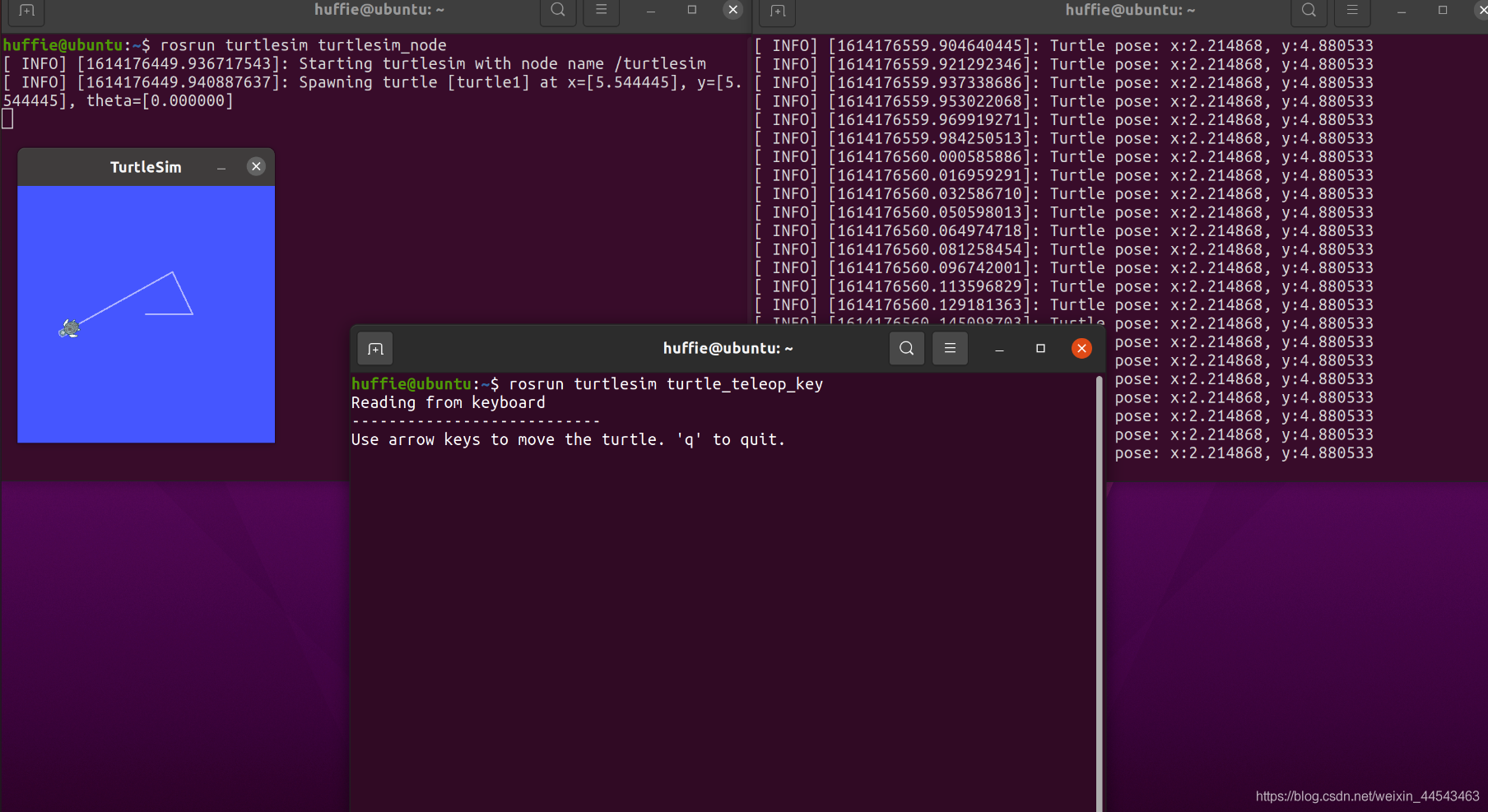
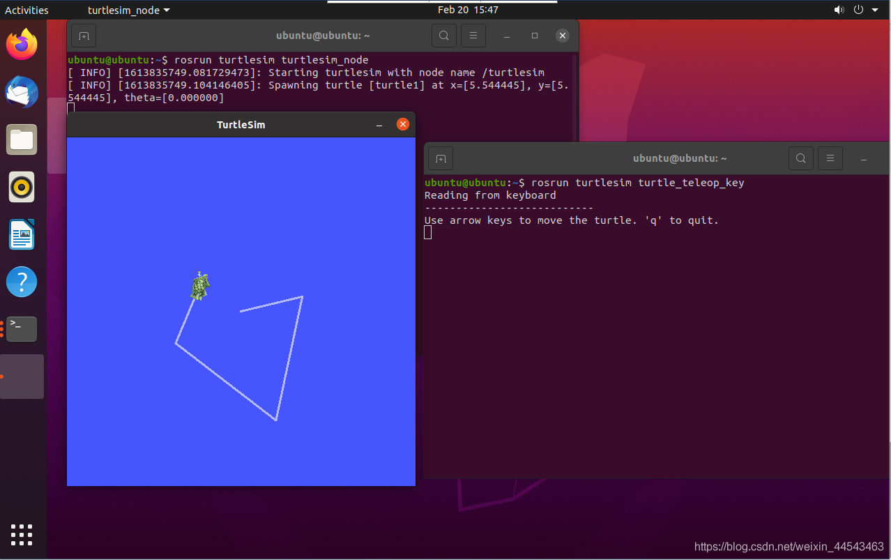
ROS Master contains two nodes: a Subscriber (turtlesim) and a Publisher. The Publisher is implemented in code to publish a Message containing linear velocity and angle. The Message is transmitted through a Topic channel to the Subscriber, thereby controlling the turtle's movement.
In ROS_Master, you can publish and subscribe to messages. ROS_Master contains two nodes: a Subscriber (turtlesim) and a Publisher. The Publisher publishes Messages programmatically. The Message content includes linear velocity and angle, and it is passed to the Subscriber through the Topic pipeline, thereby controlling the turtle's movement.
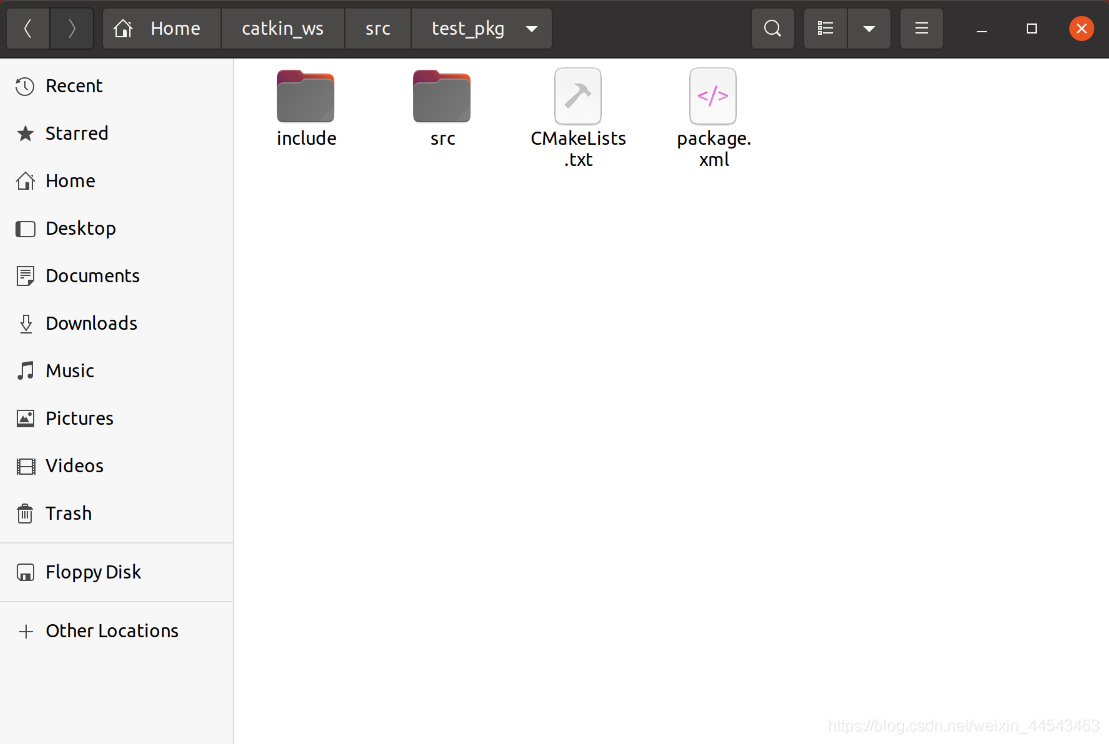
A workspace is a folder that holds project development files, similar to a project you create in an IDE on Windows. Folders in a workspace include …
roscore starts ROS Master and is the first command to run before starting a ROS system; rosrun runs a node in a package. It takes two arguments: the package name first and the node name second.
Add the ROS software repository: open Software & Updates and select the first four download options. Make sure all of them are checked, or dependency issues will occur during installation. Then run the following commands to add the software repository and public key.
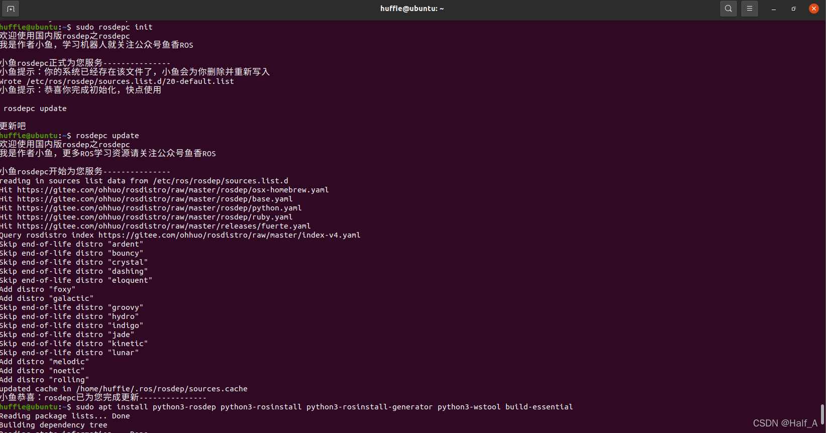
The ROS installation process is covered in my previous blog post, Installing ROS_Noetic on Ubuntu20.04. During installation, rosdep_init reports 【ERROR_cannot download_default_sources_list_from…Website_may_be down.】. rosdep_update always times out and cannot update. I finally found a reliable solution that works.
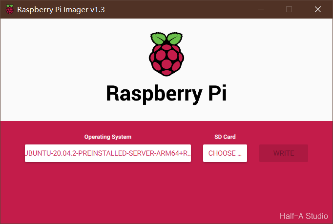
Go to the official Ubuntu website and download the Ubuntu installation package for Raspberry Pi. Use DiskGenius to format the SD card, delete all sectors, and then format it. Download the official imaging tool, select the .xz file you just downloaded as the image, select your SD card, and write the image. Then configure the Ubuntu environment...
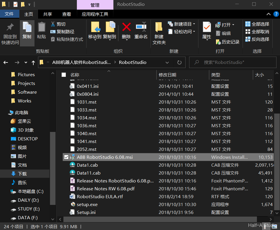
Cloud drive link: https://pan.baidu.com/s/1yUpRG146dUXC9Gj1D94AHw, extraction code: rsaz. Extract the installation package, run ABB RobotStudio 6.08.msi, and follow the prompts step by step to install it. After installation is complete, depending on your computer, extract...
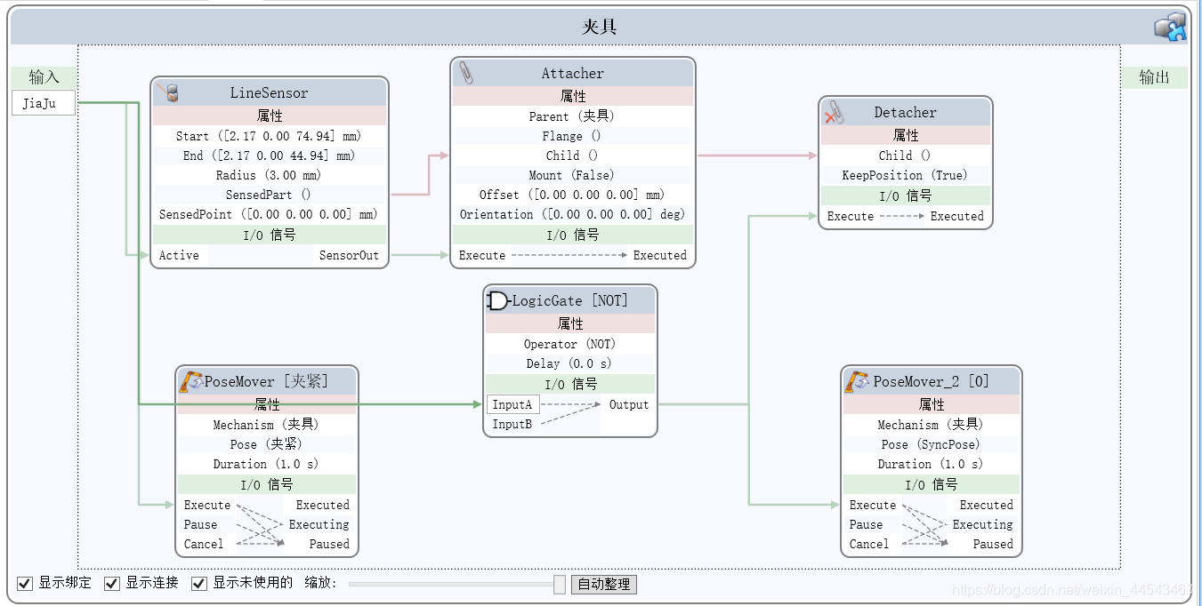
First, import an IRB2600 robot and move the gripper's local coordinate origin to the center of its top surface (where it connects to the flange). Align the local coordinates of the gripper Smart Component with the coordinates of the robot's end flange...
If you have a gripper model created with other modeling software such as SolidWorks, you can import it into RobotStudio. Here, a simple model is created, mainly to demonstrate the process of creating a dynamic gripper.
Click Create Collision Detection to create a collision check. Once created, ObjectA and ObjectB are the two groups to be checked. If objects in the two groups collide, their colors will change.
This article covers the process of creating a robot path after the mechanical model and robot system have already been created. The project files have been uploaded to a cloud drive, including the initial project file (03Practice_init.rspag), the completed project file (03Practice.rspag), and model files.
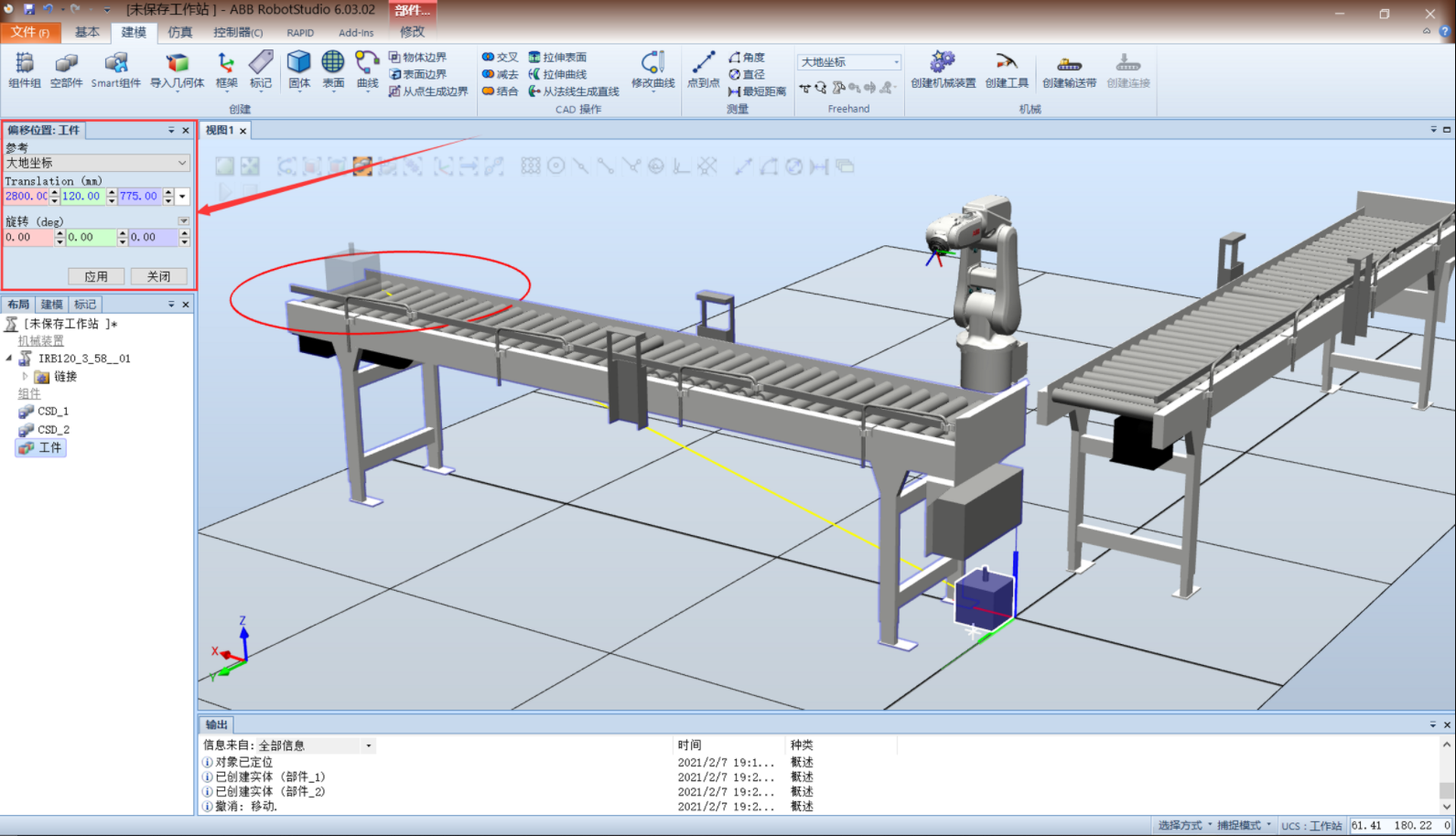
Start by building the mechanical structure of the system. Import two conveyors, rotate the second conveyor 90° about the z-axis, then offset it -3200mm along the y-axis. Import the IRB120 robot and move it to a suitable position. Create a workpiece model...
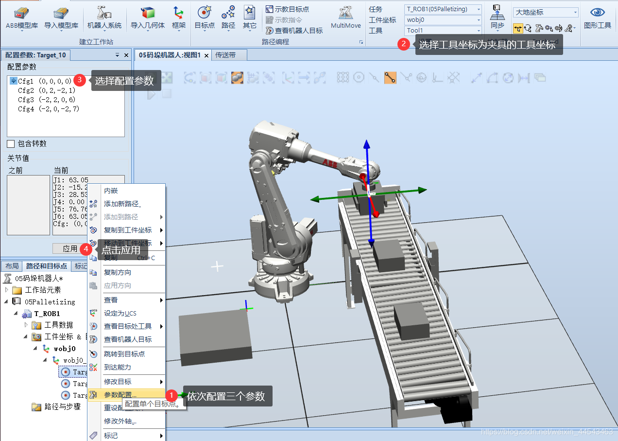
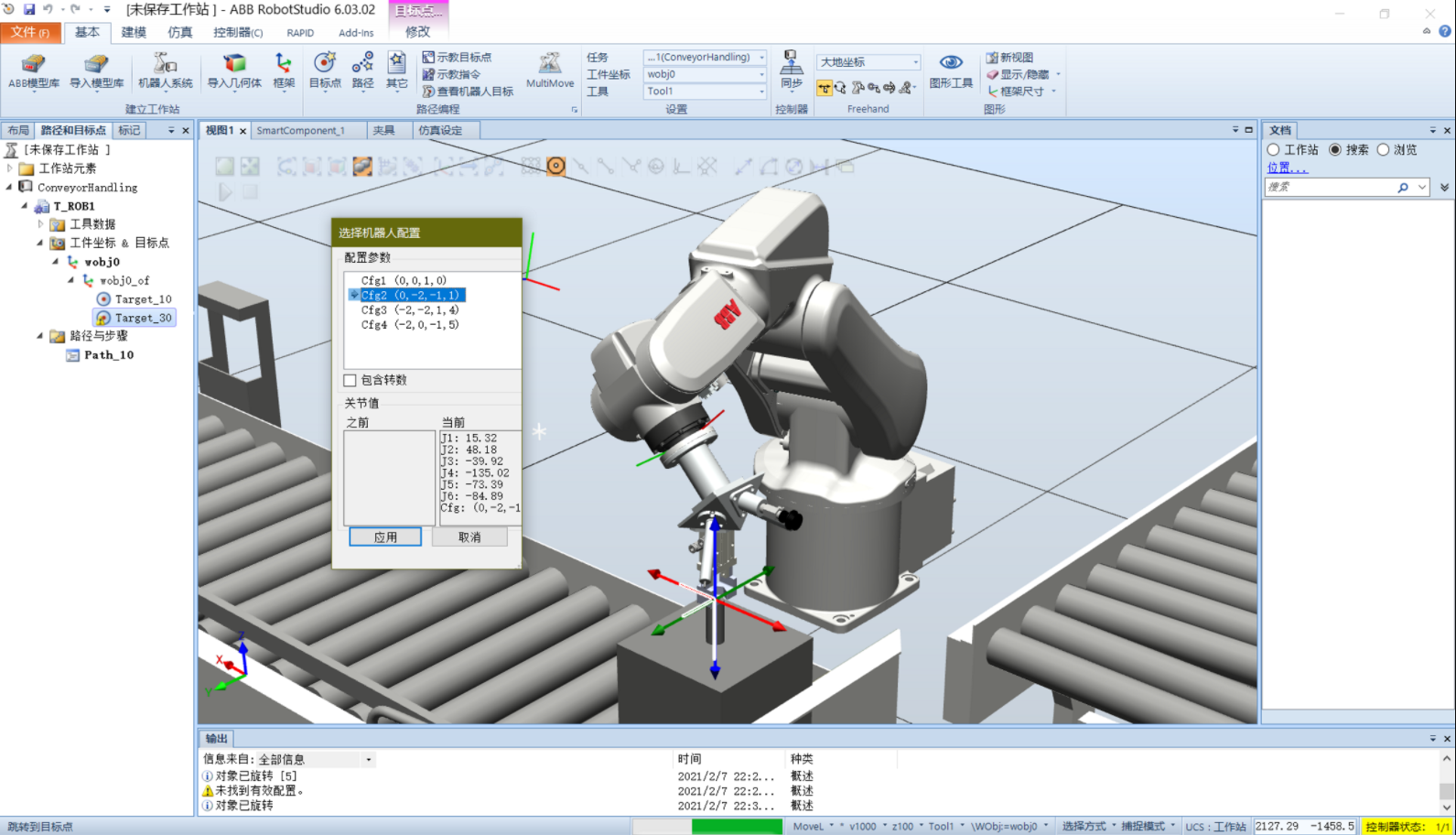
When creating a target using Create Target under Paths and Targets in RobotStudio, you may sometimes be unable to jump to the target because no valid configuration is found. Solution 1: Under Basic - Settings, select the correct tool coordinate system, such as the gripper's tool coordinate system.
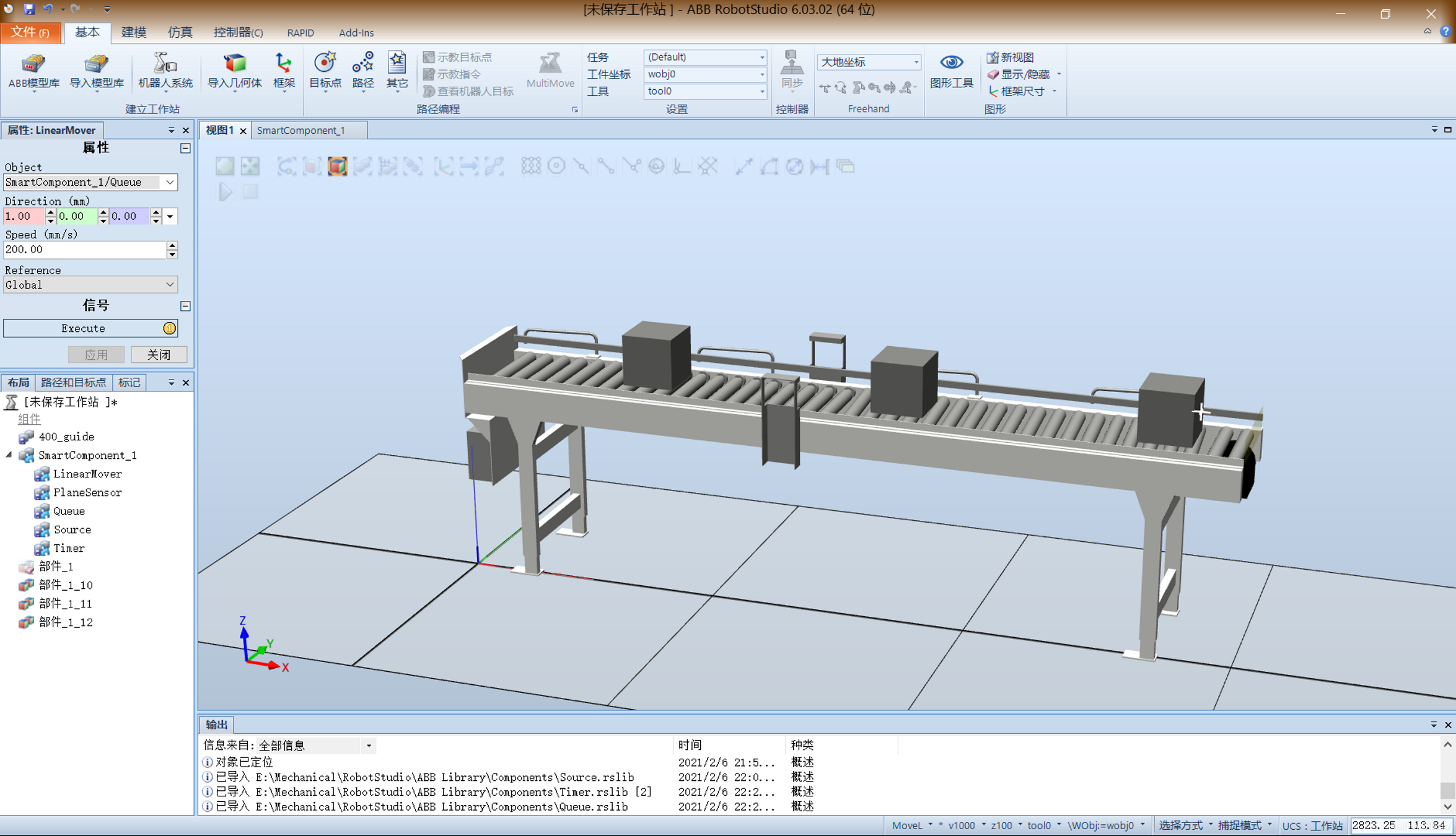
Create a new station and import a conveyor from Equipment. Create a cube to serve as the object carried by the conveyor. Drag the small cube onto the conveyor at the desired position, using Snap and Set Position to position it precisely...
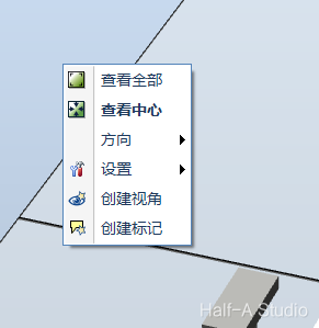
When using ABB RobotStudio, dragging the mouse to pan the view may sometimes suddenly become very slow. Right-click a blank area of the station, then click View All or View Center. This resolves the issue.
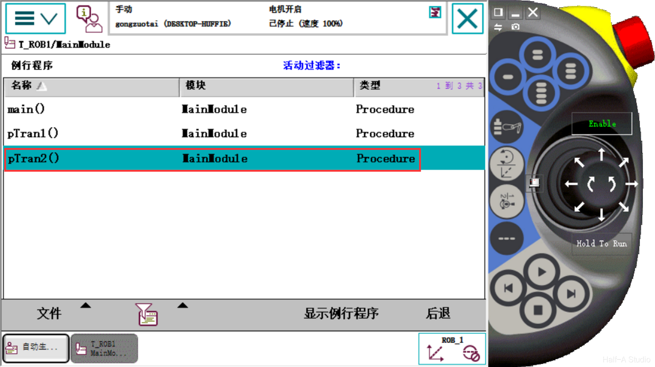
When a program is relatively complex, or when repeated sections appear within a program, modular program design is often a viable approach. In RobotStudio, you can call different routines from the main program to keep the code logic clear.
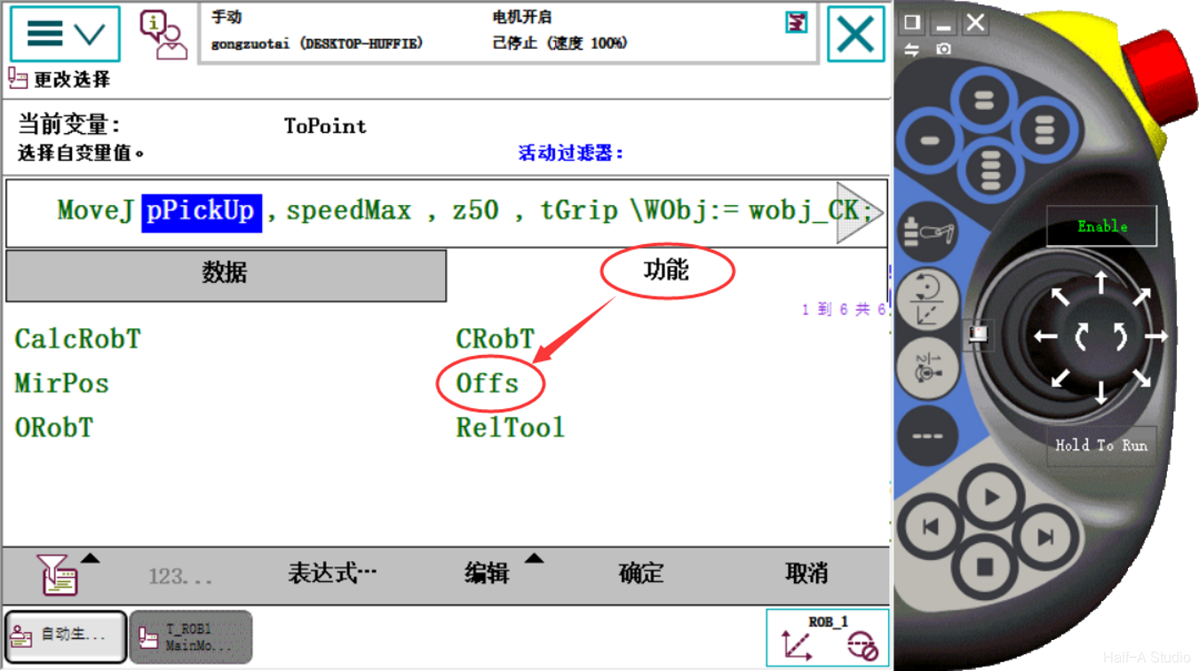
The Offs instruction offsets coordinates based on the currently selected workobject coordinate system and a reference point. Click the robtarget data to offset and select Function - Offs to configure the coordinate offset.
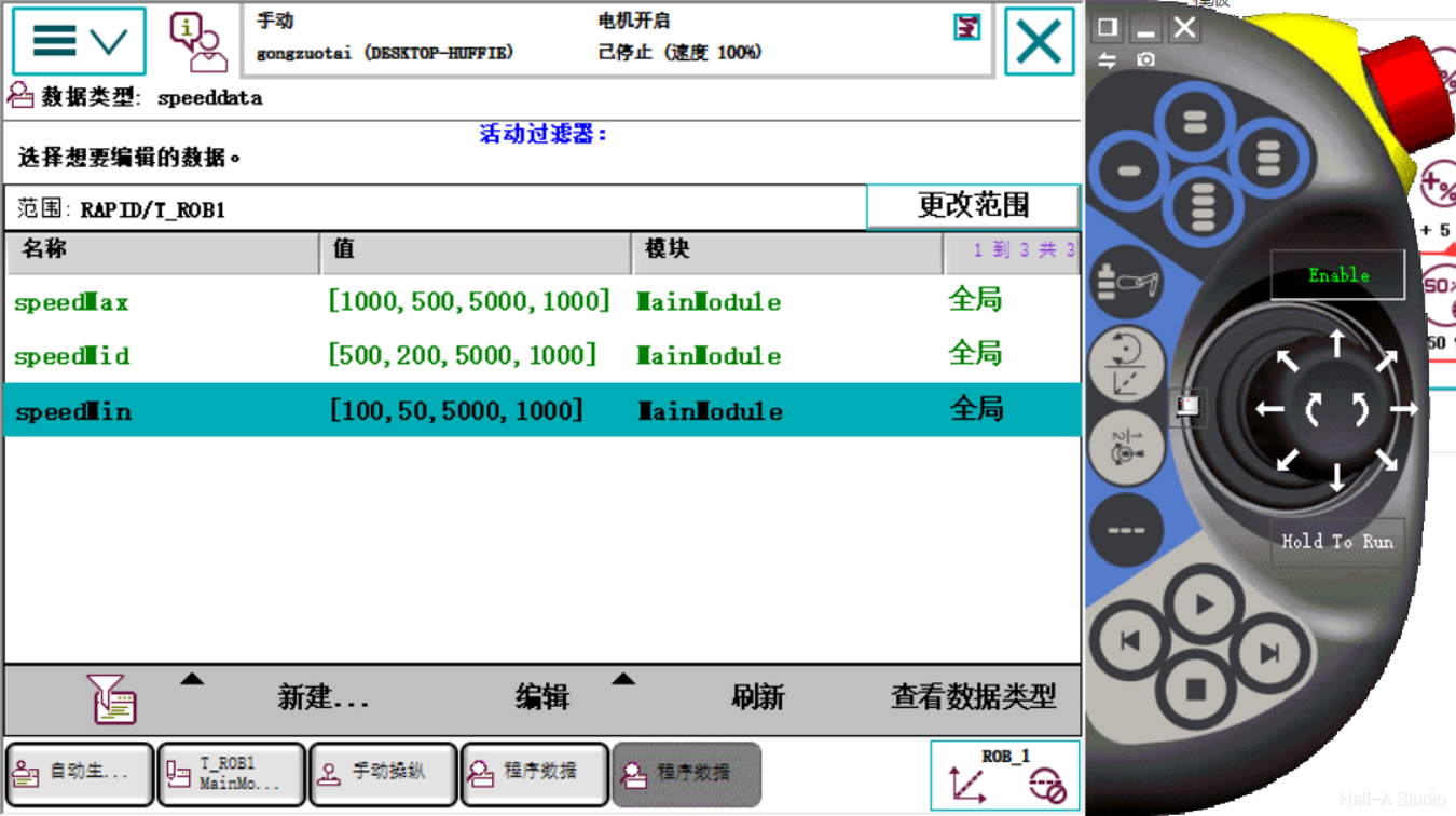
In manual mode, the maximum speed is limited to 250mm/s. The v1000 speed used in a program is very fast both in simulation and on a physical robot, so the robot's motion speed and delay time need to be configured.
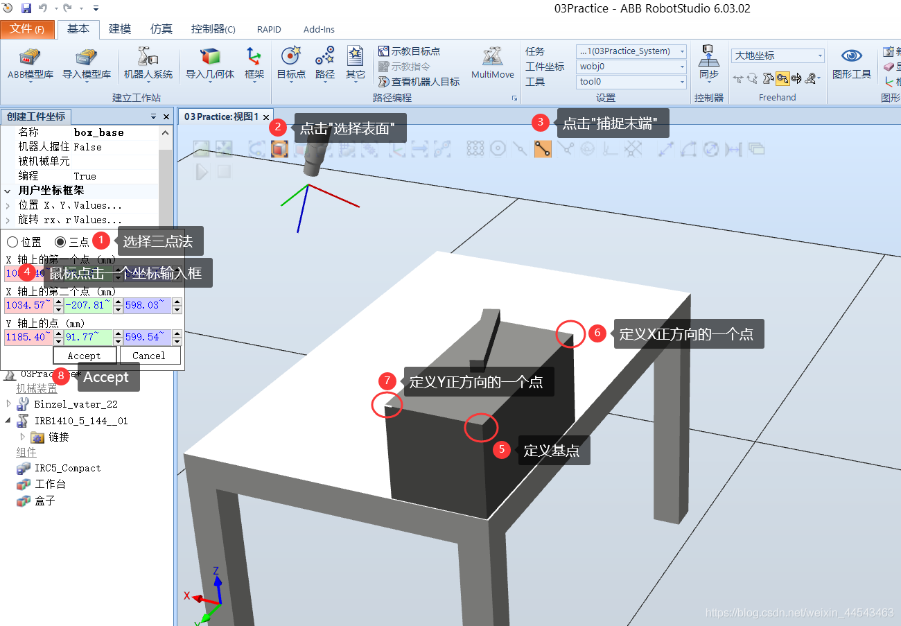
Create a Cartesian coordinate system at any position and orientation on the target workbench; this is called a WorkObject coordinate system. By creating WorkObject coordinate systems at different locations, the same program can perform the same process at those different locations.
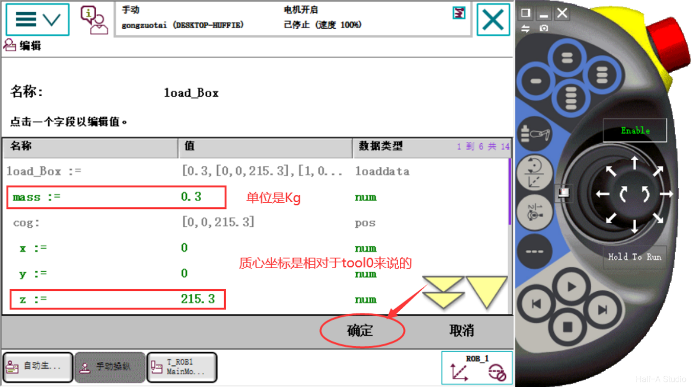
After the gripper picks up a workpiece, the system load changes. This difference may not be obvious in a simulation, but it must be taken into account in a real system.
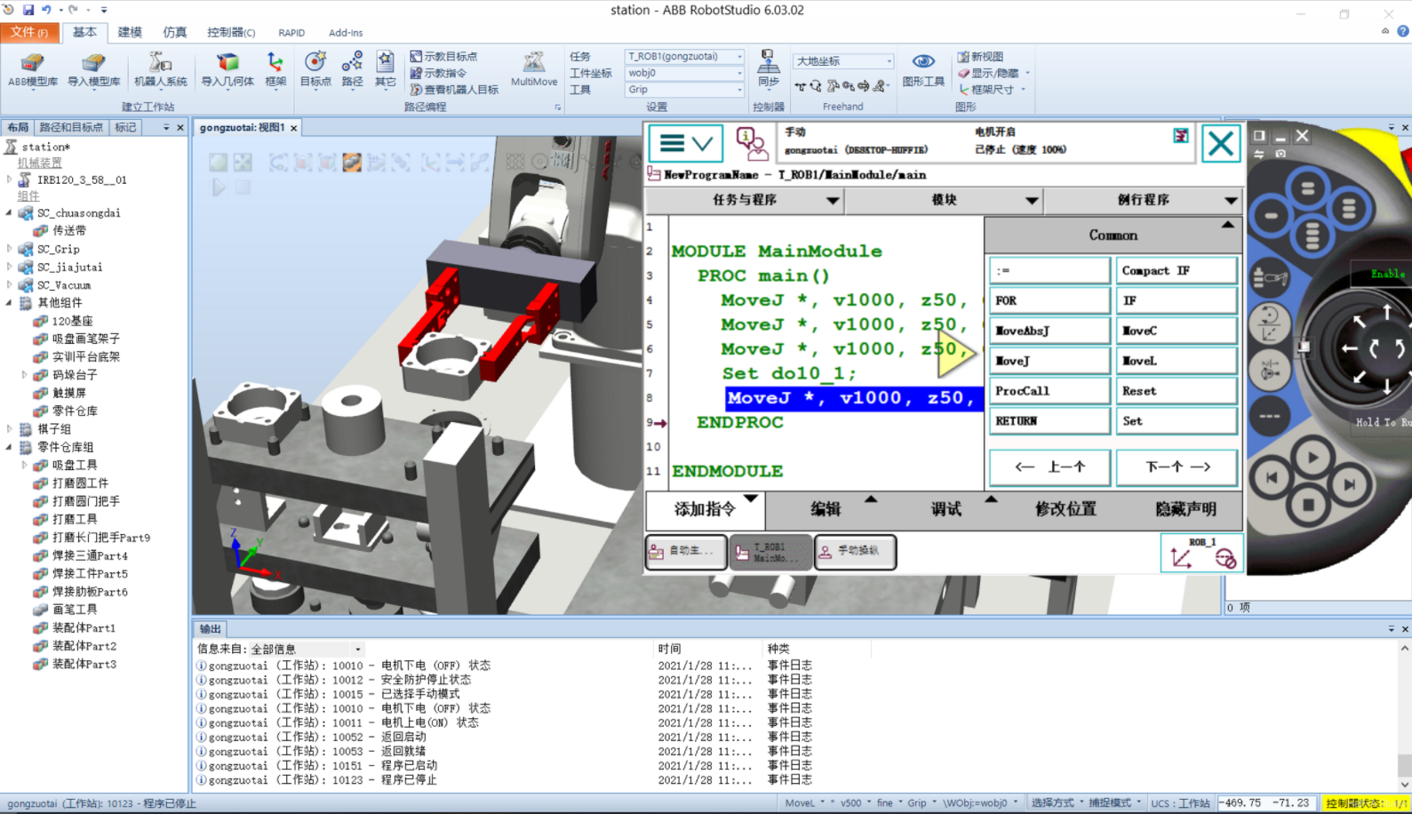
MoveJ moves the robot to a position. Set/Reset controls external devices. Add a MoveJ instruction at the initial position to move the robot gripper directly above the workpiece, then add another MoveJ instruction (adding a waypoint above the workpiece prevents the robot from grasping directly and possibly colliding with the workpiece from the side).
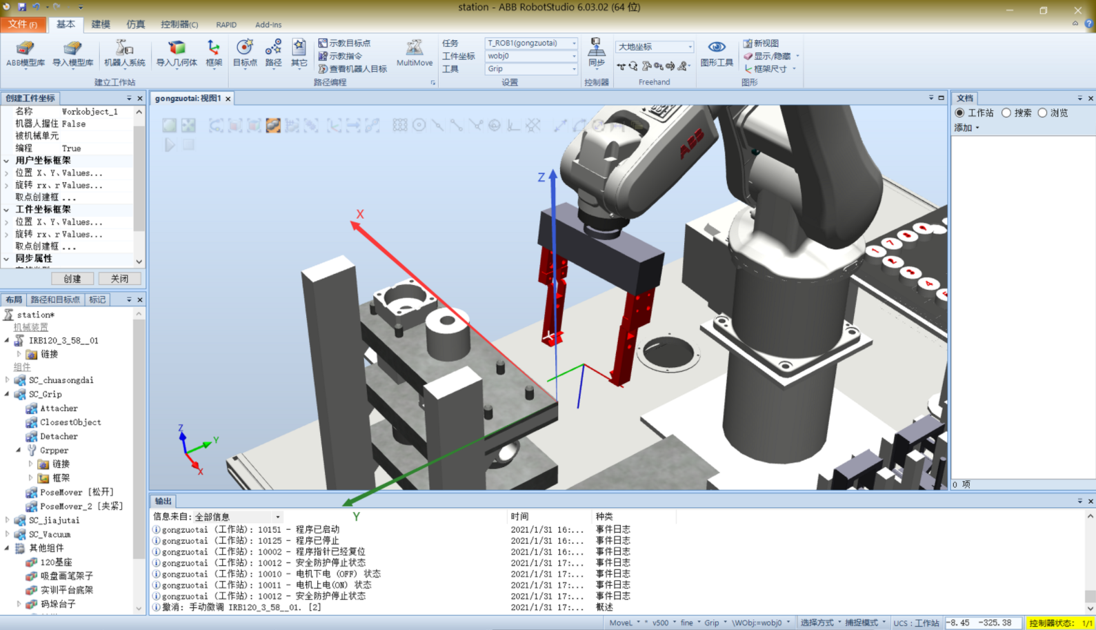
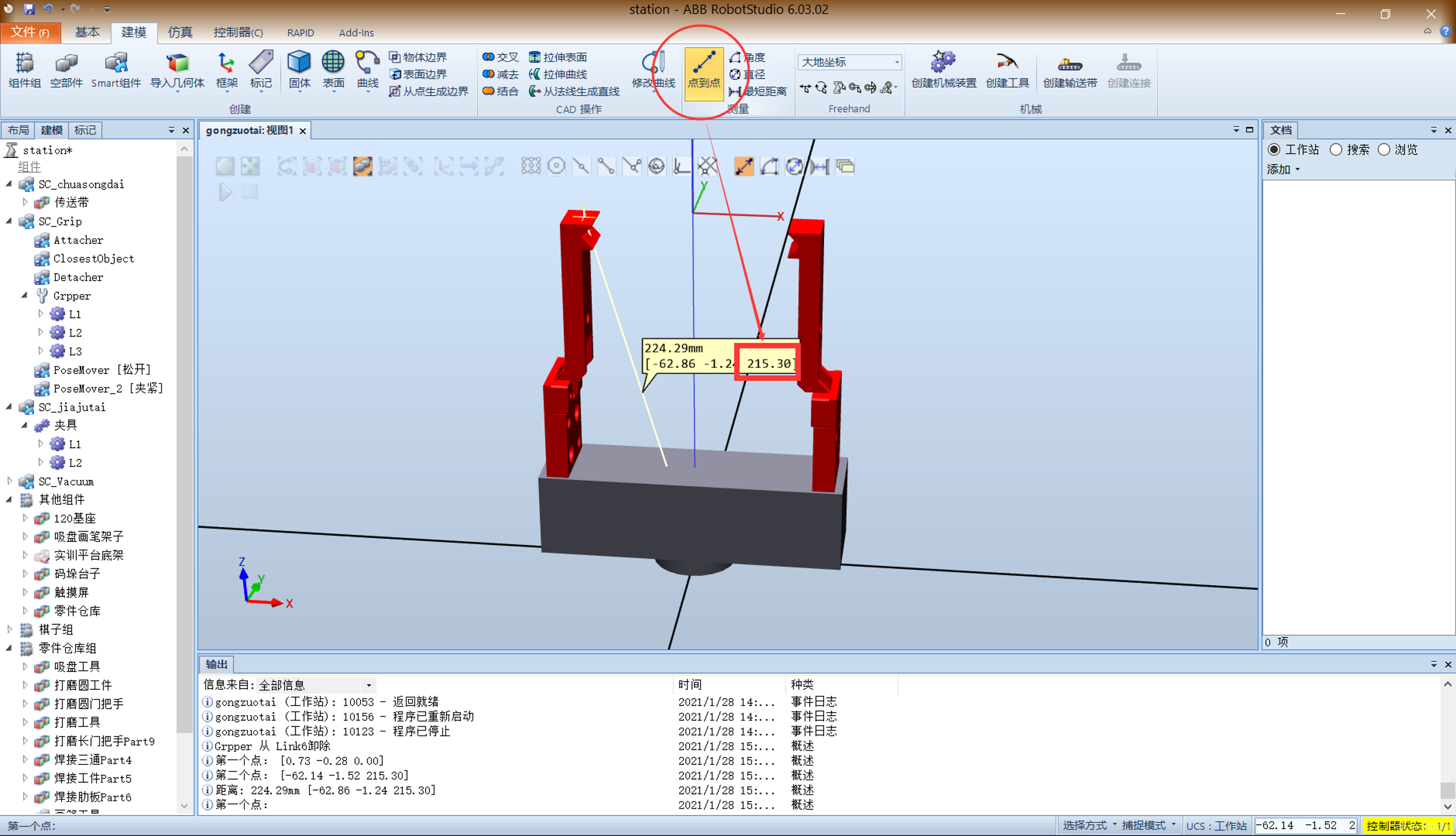
Remove the gripper and measure the coordinates at the gripper tip. Click Modeling - Measure - Point to Point, select the gripper's base and end faces, and record the resulting z-coordinate value. Reinstall the gripper on the end of the robot. Open the Virtual FlexPendant, go to Manual Operation - Tool Coordinates - New, change the name, and click Initial Value in the lower-left corner. Set the first z (coordinate position) to the measured value, 215.30; set the mass parameter mass to 1; and enter an initial estimate for the second z (center-of-gravity position). Verify the coordinates, set Motion Mode to Reorient, and set Tool Coordinates to the coordinates created above. Moving the joystick shows the robot rotating about the center point between the two gripper tips.
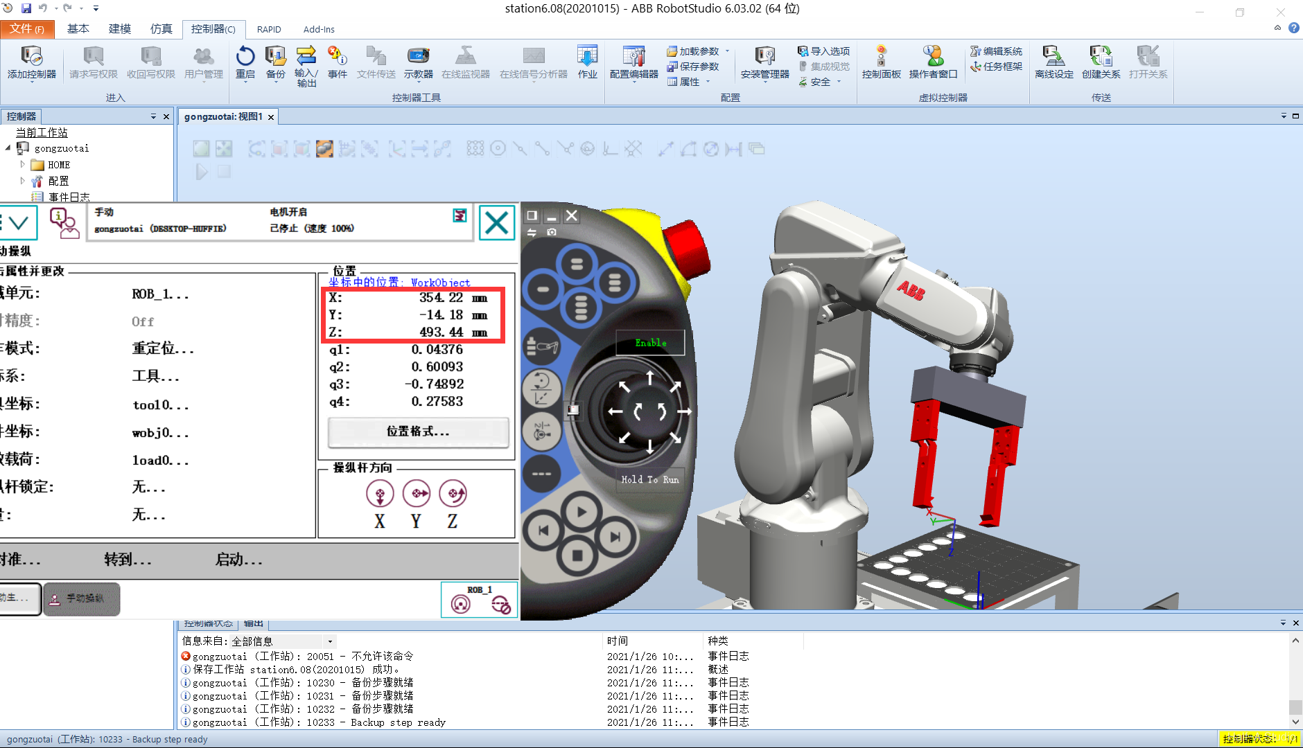
Open a robot system and the Virtual FlexPendant. Click Menu - Manual Operation - Motion Mode. Four motion modes are displayed below. The single-axis options are Axes 1-3, plus Axes 4-6; these are followed by linear operation and reorientation. Here, select Axes 1-3, then click OK. On the right side of the manual operation screen, you can see the robot's position information and joystick directions.
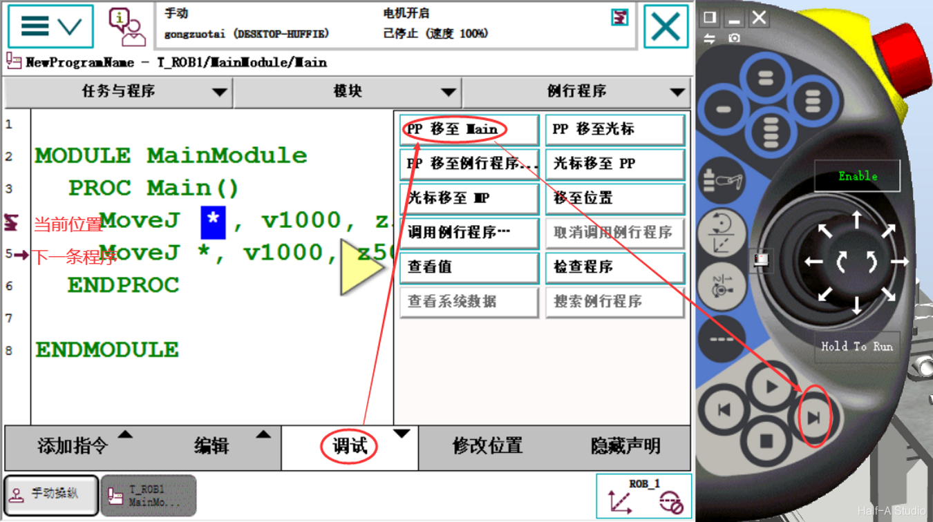
Open the main menu > Program to see the program name on the top line. T_ROB1 is a task; you can choose one task for each mechanical unit. The second level is modules, divided into system modules and program modules. Modules split the robot's required functions into separate modules—think of them like folders. The third level is routines—the programs the robot system actually executes.
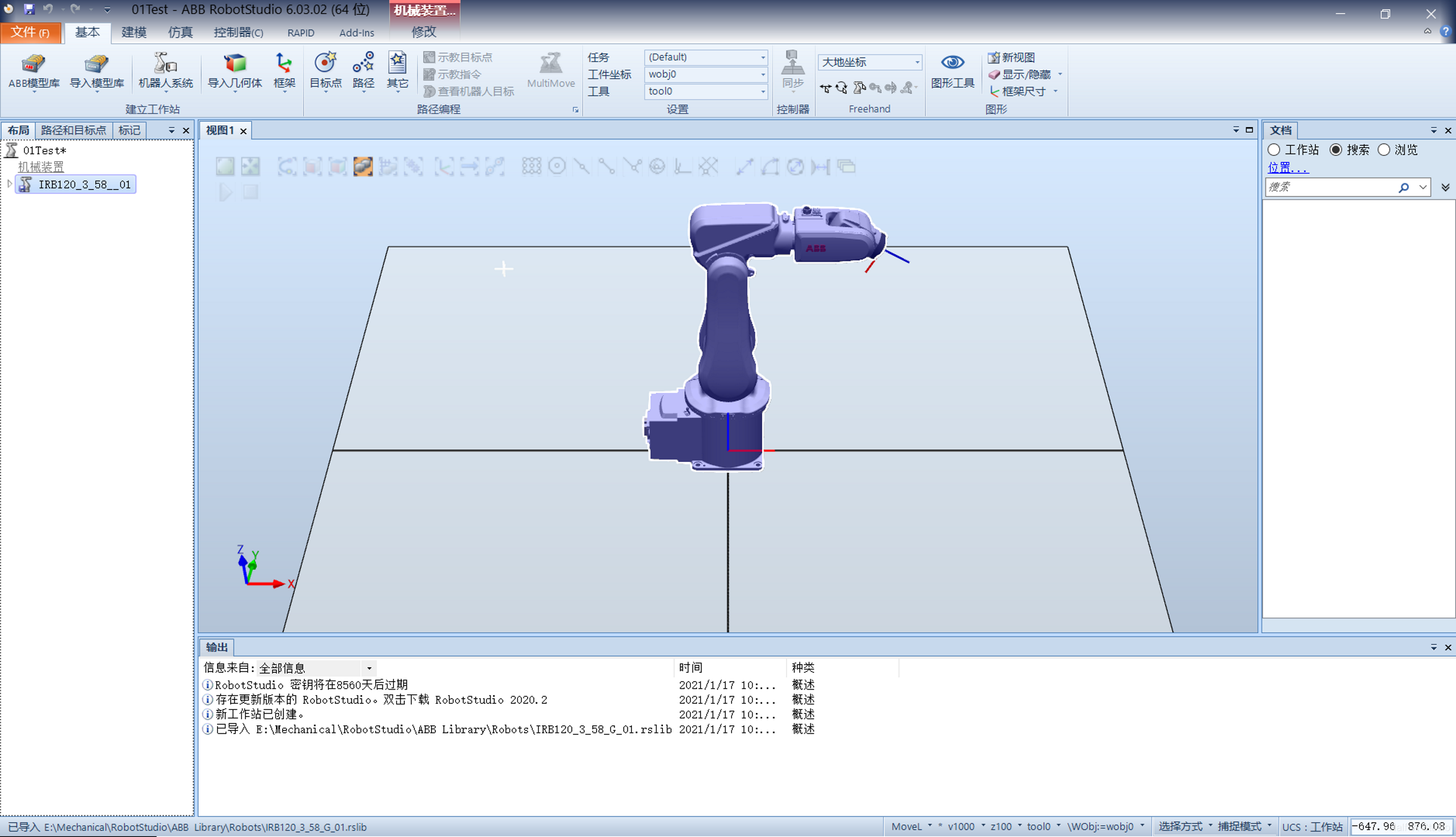
Extract the installation package, run the setup.exe program in the package, and follow the prompts to install it. The process is quite simple. After installation, double-click RobotStudio_5.61.02注册补丁.reg. Open RobotStudio to complete the installation.
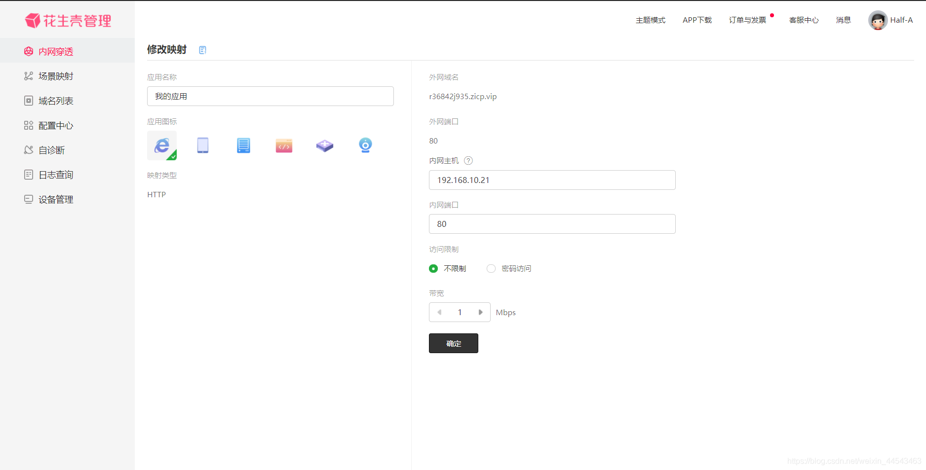
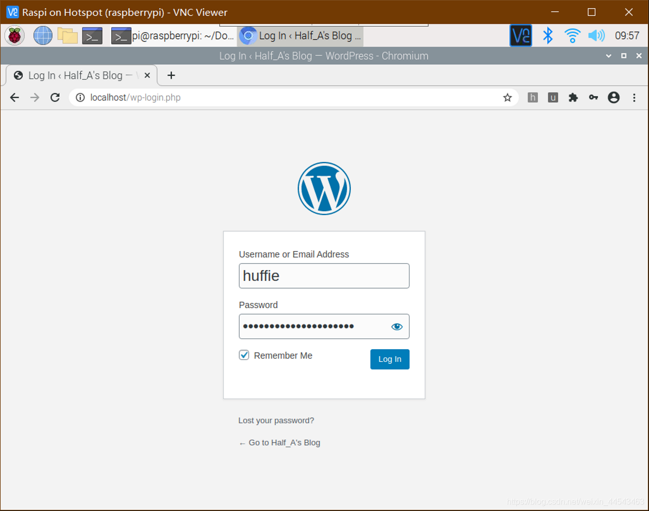
After WordPress has been installed and configured, you can access the website by entering localhost or the Raspberry Pi's IP address in a browser. However, it still cannot be accessed from the external network (outside the same router). The purpose of NAT traversal is to allow computers on the external network to access your website. To make the setup less difficult and complex, I used PeanutHull.
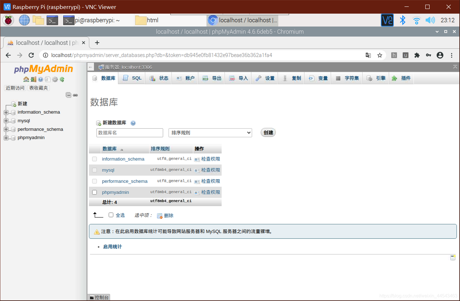
Download the installation package from the official WordPress website, extract it, and place the contents of the worpress folder in the html folder. Enter localhost/phpmyadmin in your browser to open phpMyAdmin, enter your phpMyAdmin username and password, click the Databases tab, create a new database, enter a database name, and click Create. No database tables are needed for now.
Setting up a personal website on a Raspberry Pi mainly involves the following steps—setting up a LAMP server (Linux + Apache + MySQL + PHP) and creating a database user (this step requires installing PhpMyAdmin and using SQL statements to add a MariaDB database user).
Raspberry Pi installation, configuration, and remote access mainly involve the following steps—preparing the TF card, downloading and writing the image, determining and accessing the IP address, updating and configuring package sources, and implementing Windows remote access. At this point, the initial system installation is complete and you can enter the graphical interface.
Case structures are similar to if…else… and switch structures in C and are mainly used to select among branches of program logic. A case structure contains two or more subdiagrams or cases. Only one case executes at a time. Right-click the case structure border to add, duplicate, delete, reorder, or select the default case. Multiple input/output tunnels can be created.
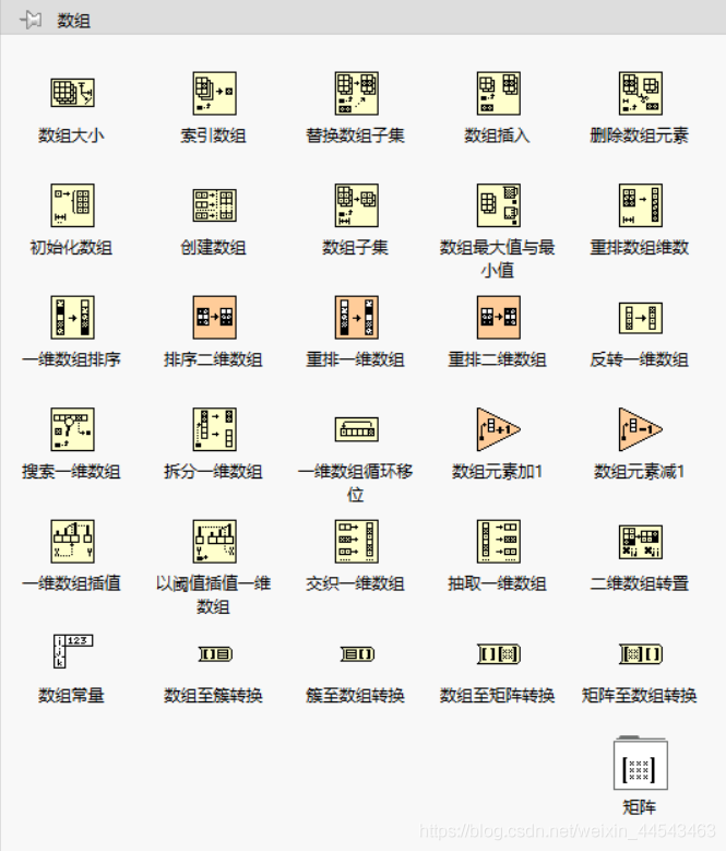
When processing a series of similar data and performing repeated calculations, consider using an Array. An Array groups data elements of the same type. Place an Array shell on the front panel and drag a data object or element into the shell to create an Array. Array functions such as Array Size, Index Array, Build Array, Array Max & Min, Sort, and Split Array can all be performed with Array functions.
Property nodes provide access to object properties. In applications that may need to programmatically change the appearance of front panel objects in response to specific inputs, these changes can be configured by editing property nodes. Right-click a control on the block diagram to create a property node. To configure multiple properties, drag the top or bottom border to add properties. A property node executes its properties from top to bottom.
The purpose of variables is to transfer data between parallel loops. Shift registers can transfer data generated by the previous iteration to the next iteration. Right-click the loop border to add a shift register. The shift register on the right stores the data at the end of each iteration, while the shift register on the left provides the stored data to the next iteration.
A While Loop executes at least once, while a For Loop can execute 0 times. A While Loop automatically outputs the value from the last iteration, while a For Loop automatically outputs an array. You can right-click the border of a While Loop and convert it to a For Loop from the shortcut menu.
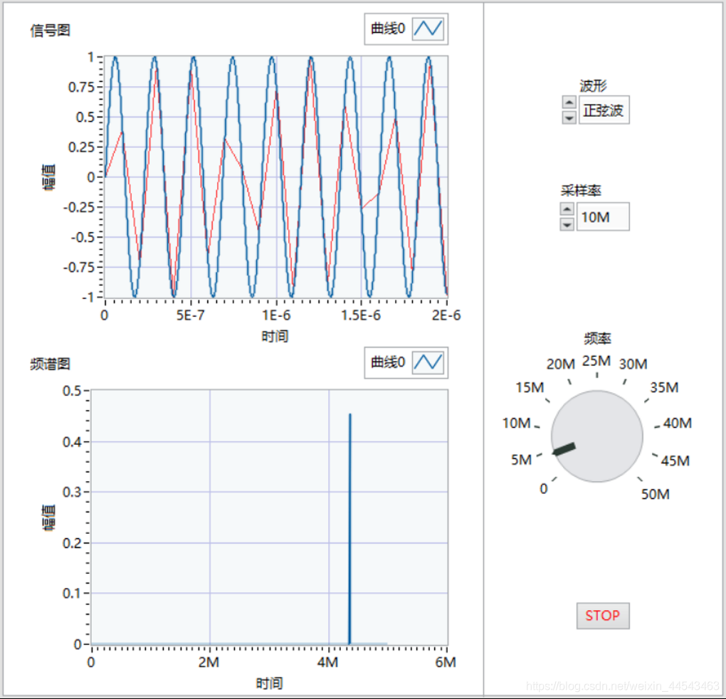
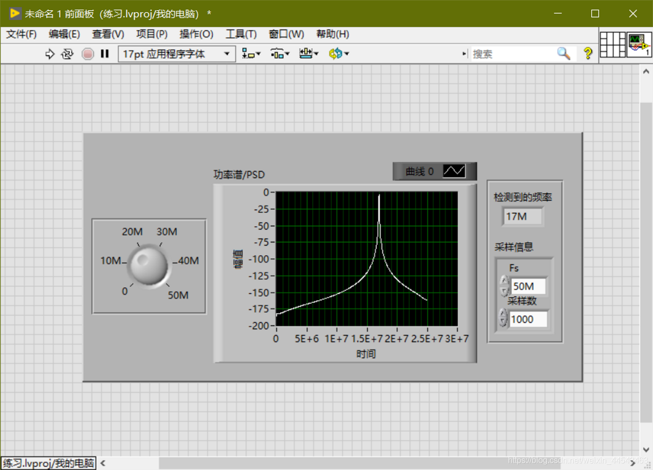
Generate a sine-wave signal with a frequency of 0-50M; choose a sampling rate of 10M/50M/100M; detect the signal frequency; output the sampled signal's power spectrum; and restart averaging if the frequency or sampling rate changes.
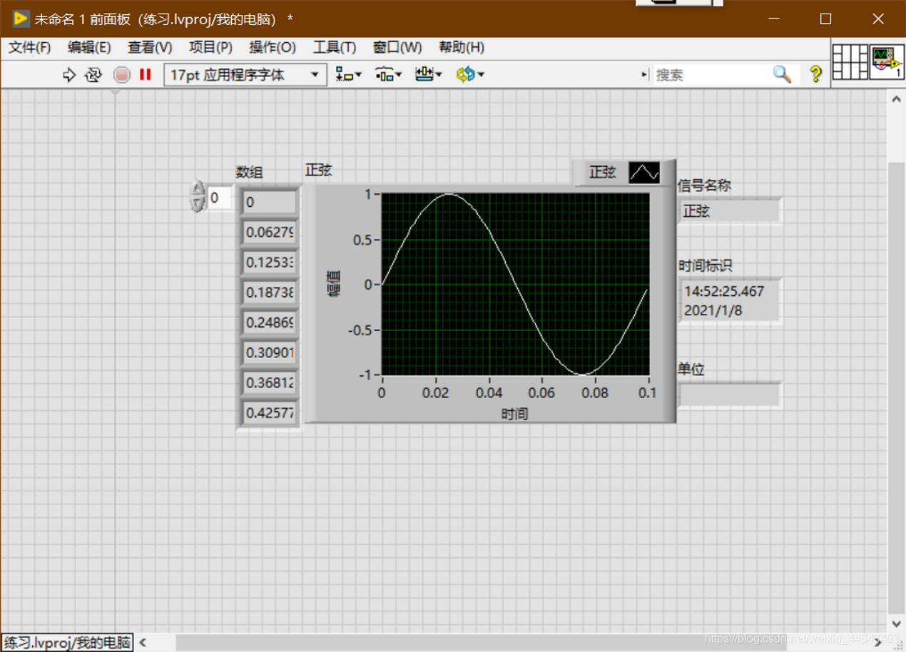
In LabVIEW, the dynamic data type is shown in dark blue. Only Express VI can produce and receive ExpressVI. Use the Get Dynamic Data ExpressVI to retrieve the properties of dynamic data, and use the Set Dynamic Data Attributes ExpressVI to set properties such as the signal name, timestamp, and time mode.
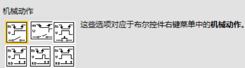
Numeric controls can represent different types of numeric values. The most important setting for Boolean controls is the mechanical action. The display type of string controls can be changed from the shortcut menu. To add items to a control's drop-down list and reorder them, right-click an enum or ring control and select Edit Items from the shortcut menu, or click the Edit Items tab in the Properties dialog box.
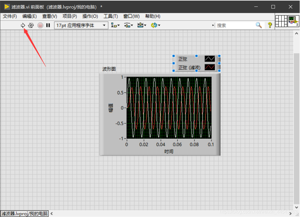
Place an Express VI on the block diagram, configure the dialog box that appears, wire the Express VI, then save and run the VI.
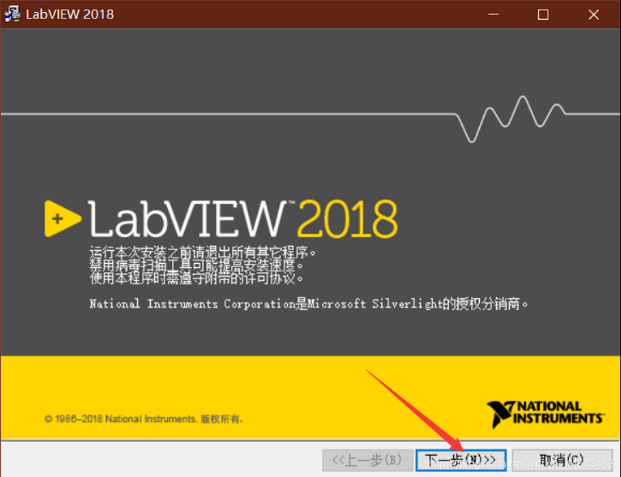
If you need a different version, see the resources page. Download the LabView2018.zip archive from Baidu Netdisk. Before installation, create a new folder for the LabVIEW installation path. It is best not to install it in the root directory of a drive.
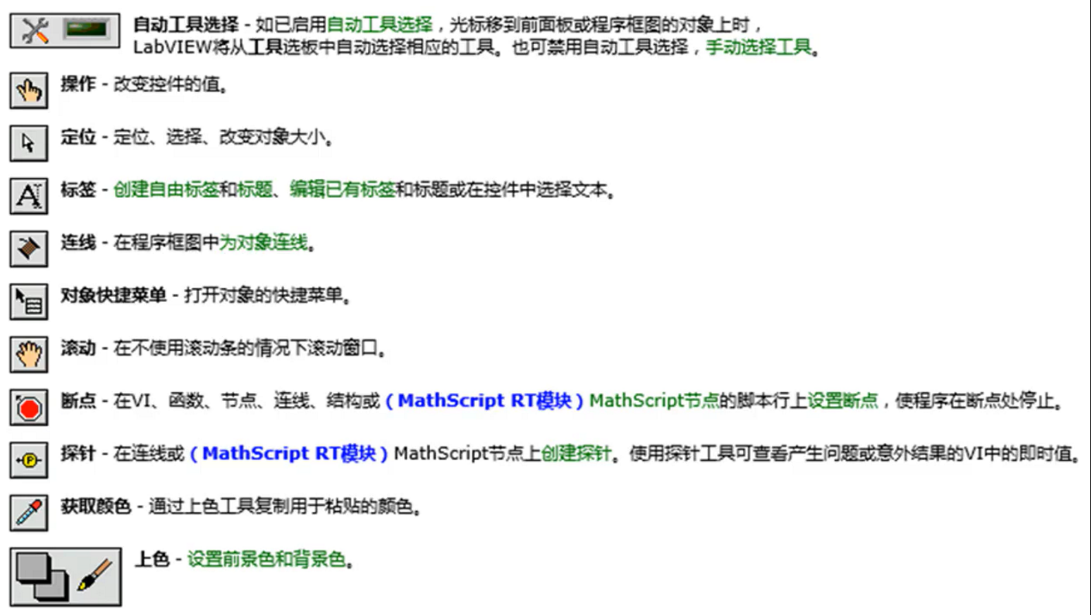
Controls come from the Controls palette. Right-click to open the Controls palette. You can add a control to the front panel by clicking it or dragging it. A block diagram consists of terminals (from the front panel), subVIs, functions, constants, structures, and wires.
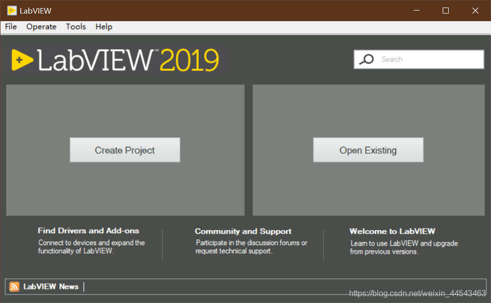
This release is the English version. For the Chinese version, see the resources page. Download the LabView2019.zip archive from the cloud drive, extract it and open the corresponding 64-bit or 32-bit folder, then extract the ISO file inside that folder, open the extracted folder, and double-click install.exe to install.
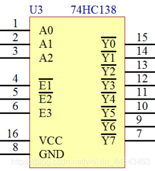
When designing MCU circuits, the number of MCU I/O pins is limited and sometimes cannot meet our design requirements. To control more devices, we need peripheral digital chips for pin expansion. A common choice is the 74HC138, also called a three-to-eight (38) decoder.
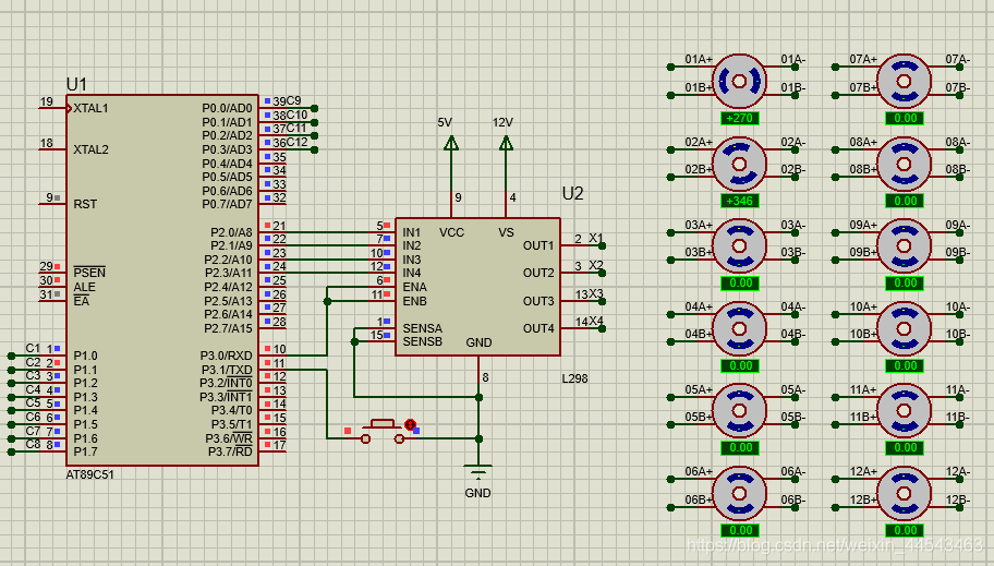
The CD4066 is a quad bilateral analog switch. Connect the four inputs of the CD4066 to the L298N outputs and the CD4066 outputs to the stepper motor's A+, A-, B+, and B- terminals. Tie all four control pins to one MCU pin so a single pin can switch all four switches on the CD4066 together, enabling stepper motor selection.
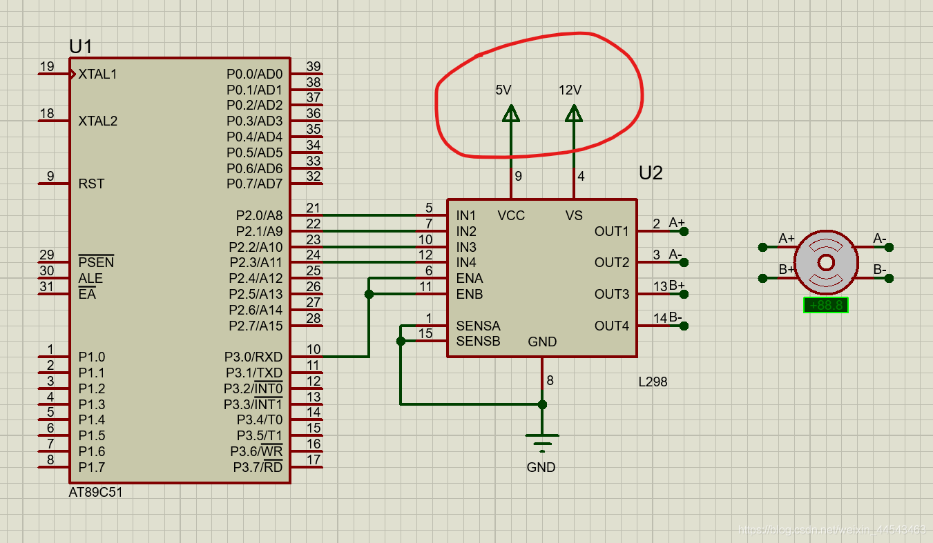
Solution: Choose Design—Configure Power Rails. Under Power Supplies, add the power supply that is not connected to a net to the list of connected nets.
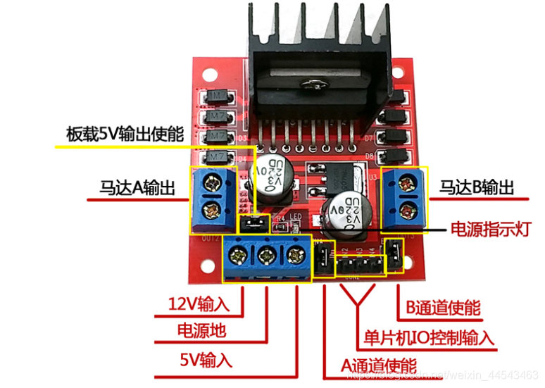
A microcontroller cannot drive a stepper motor directly, so an L298N is needed as the driver. This article introduces some L298N parameters, along with the drive principles and methods for a two-phase four-wire stepper motor. A simulation experiment is also performed in Proteus based on the drive principles described.
This experiment uses an ESP8266 NodeMCU. The firmware flashed is the official NodeMCU firmware. Open the official ESP8266Flasher, select the NodeMCU firmware in the Config tab, and set the flash address to 0x00000.