Contents
- 0. Introduction
- 1. Installing Isaac Sim - WorkStation Edition
- 2. Installing Isaac Sim - Python Edition
- 3. Basic Isaac Sim GUI Usage
- 3.1 UI
- 3.2 Environment setup
- 3.3 Adding objects
- 3.4 Saving and loading scenes, referencing robots
- 3.5 Joint configuration
- 3.6 Adding cameras and sensors
- 4. Python Programs
- 4.1 Basic framework for standalone Python programs
- 4.2 Controlling a mobile robot with standalone Python
- 4.3 Common Python programs and explanations
- 5. Importing URDF Models into Isaac Sim
0. Introduction
References:
Isaac Sim is a physically accurate virtual environment developed by NVIDIA and built on the NVIDIA Omniverse platform for developing, testing, and managing AI-based robots. It provides essential capabilities for building virtual robotics experiments, including importing robot models and simulating sensors such as RGB-D cameras, lidar, contact sensors, ultrasonic sensors, and IMUs.
Isaac Sim uses the USD exchange file format to represent scenes. Universal Scene Description (USD) is an easily extensible open-source scene description and file format for three-dimensional scenes. It also supports importing from URDF and MuJoCo XML files.
*.usd/*.usdc: General USD files stored and compressed in binary form, so read speed is somewhat faster.*.usda: USD files in plain text form, which are easier to read.*.usdz: USD files stored as zip archives; multiple USD files can be packaged into one.*.drc: Other custom file formats.
Isaac is an “accelerated platform built specifically for robotics and AI.”
At the hardware level, it supports various types of hardware, such as RTX GPUs. At the system software level, it depends on frameworks such as RTX, CUDA, and PhysX. At the platform level, it depends on NVIDIA AI and NVIDIA Omniverse, ultimately enabling various applications such as robot data collection and environment simulation. There are also hardware-accelerated function packages specifically for ROS called Isaac ROS.
1. Installing Isaac Sim - WorkStation Edition
The WorkStation edition is equivalent to installing a standalone application. It is convenient for opening the GUI for debugging and for developing programs through the GUI and extensions. If you want to run code this way, you need to use isaac-sim.sh in the installation directory, which limits Python environment options. For example, to run a test.py file:
~/isaacsim/isaac-sim.sh ~/path/test.pyThis article demonstrates installing Isaac Sim Workstation on a server with a display. For the workflow, see: https://docs.isaacsim.omniverse.nvidia.com/latest/installation/install_workstation.html If you use a server without a display, you can install via Docker. See: https://docs.isaacsim.omniverse.nvidia.com/latest/installation/install_container.html
Refer to Isaac Sim Requirements to check whether your system meets the requirements.
- System: Ubuntu 20.04/22.04, Windows 10/11
- GPU: Must have RT Cores, such as RTX 30 series, RTX 40 series
- NVIDIA driver: 535.129.03 or later (2024, month 10 requirement; refer to official website updates)
(1) Download IsaacSim
Open the Isaac Sim Latest Release page: https://docs.isaacsim.omniverse.nvidia.com/latest/installation/download.html#isaac-sim-latest-release
Download the latest Isaac Sim 4.5.0 package from the first row.
mkdir ~/isaacsim
cd ~/Downloads
unzip "isaac-sim-standalone@4.5.0-rc.36+release.19112.f59b3005.gl.linux-x86_64.release.zip" -d ~/isaacsim
cd ~/isaacsim
./post_install.sh
./isaac-sim.selector.sh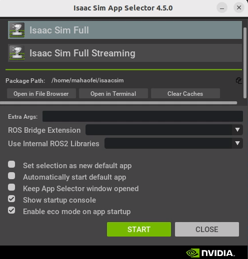
Click Start to run the main Isaac Sim program.
The first run may warm up the shader cache, which can be slow and laggy. Afterwards, you can run
~/isaacsim/isaac-sim.shto start.
2. Installing Isaac Sim - Python Edition
The Python edition installs Isaac Sim directly in a created virtual environment, which makes it easier to combine with dependencies from other codebases. In my opinion, it is more convenient for robotics development.
This section references: Isaac Sim Documents - Python Environment Installation
(1) Create a virtual environment
conda create -n env_isaacsim python=3.10
conda activate env_isaacsim
(2) Install the Isaac Sim package
First, update pip:
pip install --upgrade pipInstall the full Isaac Sim package:
pip install isaacsim[all]==4.5.0 --extra-index-url https://pypi.nvidia.comInstall the Isaac Sim cache extensions:
pip install isaacsim[extscache]==4.5.0 --extra-index-url https://pypi.nvidia.com(3) Example
Create a Python program as follows:
import isaacsim
from isaacsim.simulation_app import SimulationApp

simulation_app = SimulationApp({"headless": True})
## perform any Isaac Sim / Omniverse imports after instantiating the class
After running it, the Isaac Sim window opens.
The first run may warm up the shader cache, which can be slow and laggy.
3. Basic Isaac Sim GUI Usage
This section references: Isaac Sim UI and Workflow Tutorials
3.1 UI
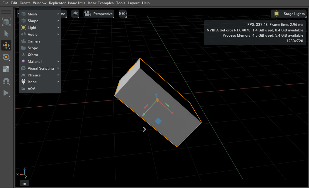
(1) Add and manipulate a cube
Click Create->Shape->Cube to add a cube:
- Select the cube and drag the axis handles to move it
- Press
Eto switch to rotation control, adjust the cube pose, then pressEagain to switch to local-coordinate rotation control - Press
Rto switch to scale control and adjust the cube shape - Press
Wto switch back to position control, adjust the cube position, then pressWagain to switch to local-coordinate position control - Press
Escto deselect the cube
All operations are reflected in the property panel in the lower-right corner. You can also enter values directly there to set cube parameters.
(2) Viewport controls
F: Center the camera and zoom to a suitable positionAlt+鼠标左键拖动: Rotate around the center of the current view滚轮orAlt+鼠标右键拖动: Zoom鼠标中间拖动: Pan the view鼠标右键拖动: Rotate the view
(3) Stage
There is a Stage panel on the right side of the window.
At this point, if you click Create->Xform, you can create an empty coordinate frame.
You can move the cube into the coordinate frame. When you then move the coordinate frame, the cube moves with it, because the cube is now a child of the Xform, and the transform relationship between them does not change when the Xform is moved.
(4) Property
The property panel (Property) is in the lower-right corner of the window. Different prims (Xform, Shape, Light) have different property data formats because they are different data types in Issac Sim.
3.2 Environment setup
(1) Gravity
Click Create->Physics->Physics Scene to add a Physics Scene to the Stage Tree on the right. In its properties, you can set the gravity direction to -Z with magnitude 9.8 (the default international standard unit).
(2) Ground plane
Click Create->Physics->Ground Plane to add a ground plane.
(3) Lighting
Every created Stage has a default light source. You can click Create->Light->Sphere Light to add an additional light source.
- In the property panel, set its Z axis to 7 and reset the default rotation of X and Y to 0
- In
Main, click the white square on the right to adjust the color - In
Main, clickIntensityto change the light intensity to 1e6 - In
Shaping, clickcone:angleto limit the light cone to 45 degrees, and clickcone:angleto set edge softness to 0.05. - To make the new spotlight easier to see, open the default light source properties and set
Main->Intensityto 300.
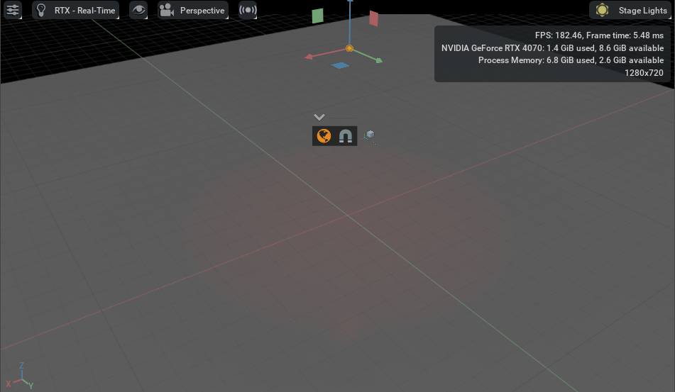
The result is shown below:
3.3 Adding objects
(1) Add shapes to the scene
- Click
Create->Shapes->Cubeto create a cube - Select the cube and raise it above the ground plane
- Click the
Scalebutton on the left, or pressR, to activate the scale widget and adjust the cube shape - In the lower-right property panel, set the object position in
Transform->translate
Likewise, we can add other shapes.
(2) Add physics properties
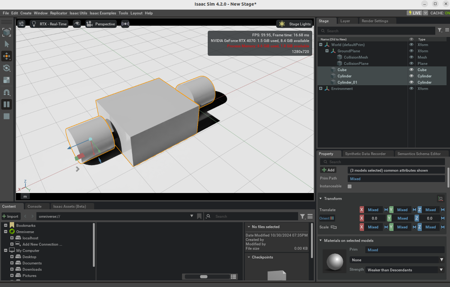
- Select all objects. In the property tab, click
+ Addand choosePhysics->Rigid Body with Colliders Presetto set the physics properties of all three shapes to rigid bodies with colliders - Click
Playand all three objects fall onto the ground plane - In the lower-right property panel, scroll down to find
Rigid BodyandCollider. You can click thexin the upper-right corner of these two APIs to remove the properties
(3) Add contact and friction
- Click
Create->Physics->Physics Materialand chooseRigid Body Materialsto create a new physics material, which appears in the Stage panel on the right - Select the material. In the property tab below, you can adjust friction coefficient, density, and so on.
- Select any object. In the property tab, find
Physics materials on selected modelsand assign the material to the part.
(4) Add appearance
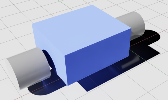
What we added above is a physics material, but the objects do not actually have color or reflectance properties (you can verify this by turning off the lights). You need to create an appearance for the objects.
- Click
Create->Materials->OmniPBR - Select any object. In the property tab, find
Materials on selected modelsand assign the appearance to the part. - You can change the base color in
Material and Shader->Shader->Albedo, or modify reflectance, roughness, and other properties to see the changes
3.4 Saving and loading scenes, referencing robots
Isaac uses the USD format for all scene files.
(1) Save the scene
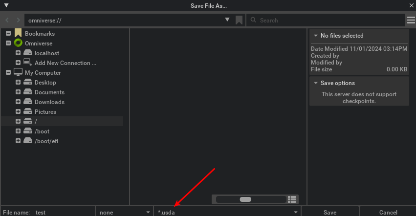
Click File->Save As... to save the current scene as a new USD file. (If you click Save Flattened As, all components are saved into the same mesh.)
You can choose the .usd format (binary) or .usda (human-readable format).
(2) Load a scene
- Click
Files->Opento open a USD file for direct editing. - Click
Files->Add Referenceto add a USD file as a reference, which cannot be edited directly. (Dragging a file into the file window also adds it as a reference.)
(3) Notes on adding referenced files
Referenced files should ideally organize all rigid bodies into a meaningful hierarchy. Using the objects from the earlier scene as an example, treat them as a two-wheeled cart:
- Use
File->Opento open the USD file you just saved - Right-click in the Stage to create an
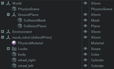
Xform. Double-click to rename itmock_robot, drag it to an empty position so it is at the same level asWorldandEnvironment, and right-click to set it as the default coordinate frame withSet as Default Prim - Rename
Cubetobody, and the twoCylinderprims towheel_left, wheel_right. Drag the rigid bodies you just created (cube, Cylinder), along with Physics Material and Looks, under themock_robotcoordinate frame - Save the file
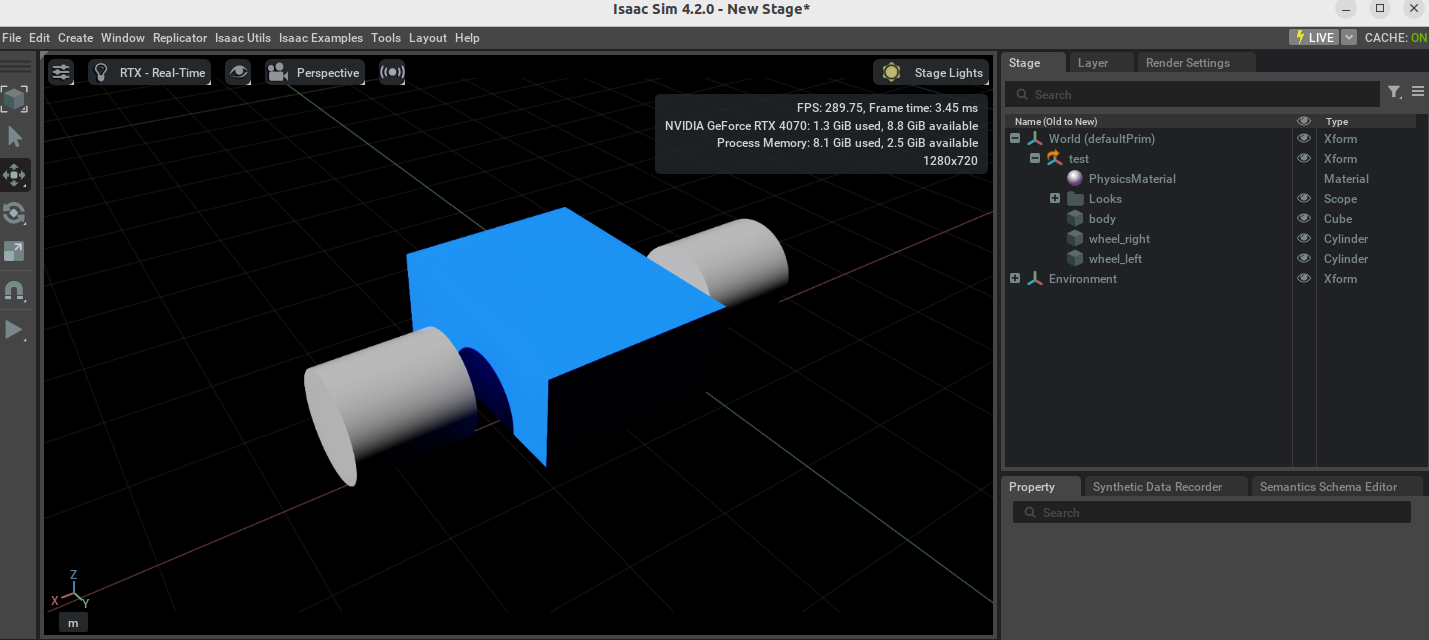
Create a new file, click File->Add Reference, and you can see that only the robot is added
3.5 Joint configuration

Use File->Open to open the file from earlier (ideally matching the figure, because joints will be added next)
(1) Add joints
- Click
Create->Scopeto create aScopefor storing joints, and rename itjoints. - When creating a joint: click the parent body first, then the child body, then click
Create->Physics->Joint->Revolute Jointto create a revolute joint. - In the joint property panel, check that
body0is the parent body (such as body) andbody1is the child body (such as wheel_right). - In the
Revolute Jointsection of the property panel, change the rotation axis toY/Zdepending on the model. - Rename the created joint to
joint_wheel_rightand drag it into thejointsscope - Repeat steps 2-5 to add the other joint
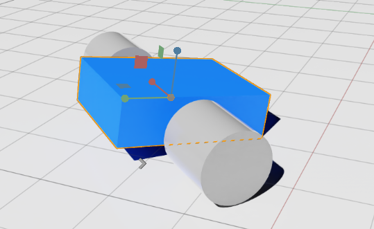
Click Play. You can observe the robot fall to the ground. Hold shift and drag the block, and you can see the two cylinders rotate and drive the robot to roll on the ground.
(2) Add joint drives
To control joints more effectively, you must add joint drives (position control or velocity control) to implement actuation.
How to add: Select a joint, click the +Add button in the property tab, and choose Physics->Angular Drive to add a drive to the joint. Scroll down in the property panel to find Drive and set its properties.
- Position control: set high stiffness and zero damping
- Velocity control: set high damping and zero stiffness
For these wheels, you can set high damping such as Damping=1e4, and set the target velocity to Target Velocity=200. Click Play to see the robot move.
(3) Add Articulation joints
Articulation is another type of joint in Issac. Unlike a joint, it is a joint group composed of a series of joints.
How to add: Select the robot base frame mock_robot. In the property tab, click +Add and add Physics->Articulation Root
That completes the setup.
(4) Add a controller
This part is mainly for testing.
Click Issac Utils->Common Omnigraphs->Articulation Velocity Control to add a velocity control graph.
Set Robot Prim to the robot base frame mock_robot
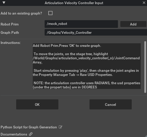
In the Stage, click Graphs->Velocity_Controller->JointCommandArray, modify Input0 and Input1—for example, set them to opposite values to make the robot turn in place with differential drive—and click Play to see the effect.
3.6 Adding cameras and sensors
(1) Create a camera
Click Create->Camera. A camera is created in the Stage panel, and a gray frame appears in the viewport representing the camera view.
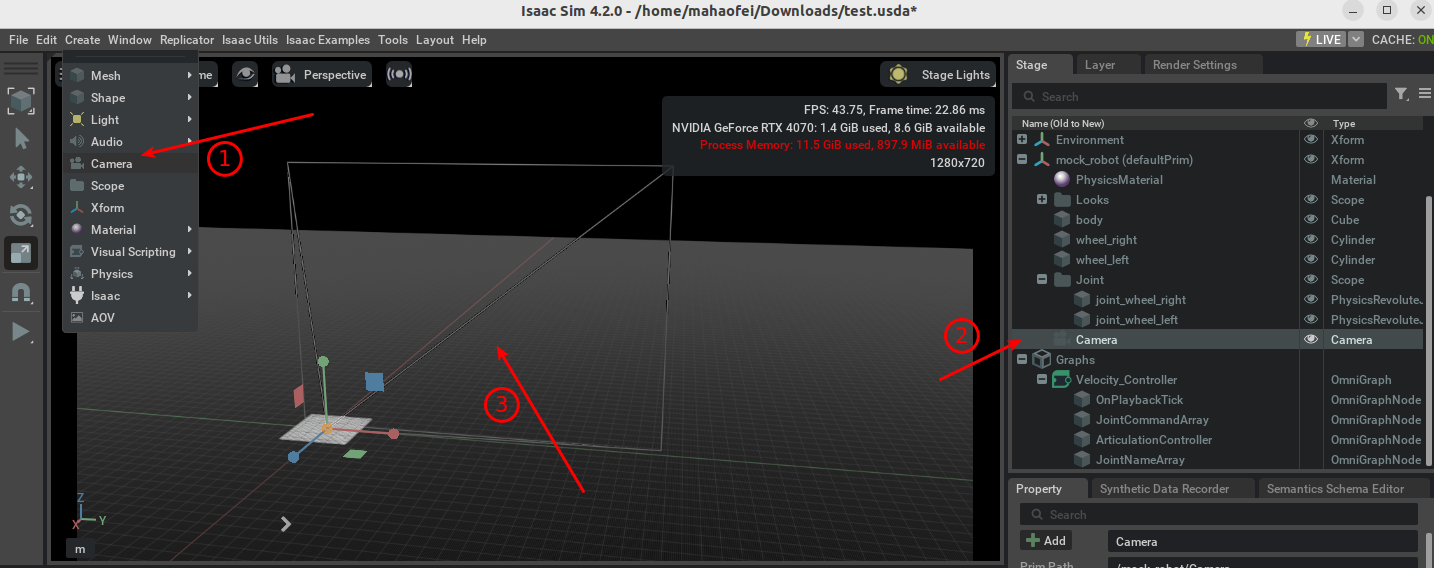
You can adjust the camera position like a normal rigid body.
(2) Camera extension
The camera extension can create different visualization views from a camera, show camera coverage, and help you inspect and design camera poses.
You can click Issac Utils->Workflows->Camera Inspector to open the camera extension
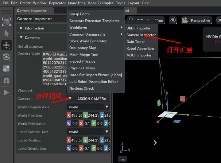
You can see a Camera State section in the panel, which shows the camera position and pose and is helpful when writing code.
(3) Create a camera viewport
Click Create Viewport in the panel to create a viewport window for the camera view, as shown below:
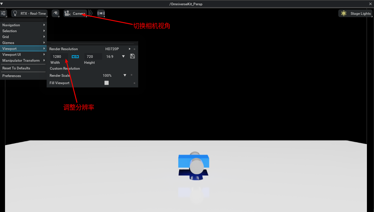
In that window, click the Viewport option in the upper-left menu to adjust the camera resolution.
If you move the camera in the simulation environment, the camera state properties update automatically.
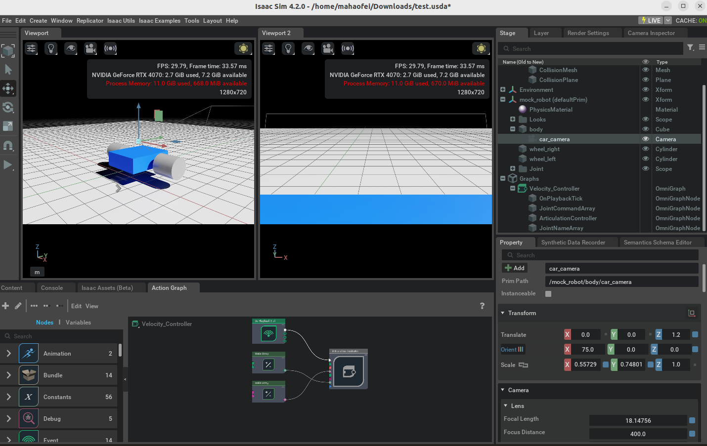
(4) Attach the camera to the robot
For example, suppose you need to add an onboard camera, fix it to the body, and make it follow body motion:
- Rename the newly added camera to
car_camera - To make the camera easier to observe, you can click
Window->Viewportto open theViewport2window, then click the movie-camera button above to switch it to thecar_cameraview (note: select mock_robot and press f inside the viewport to help center the view) - In the Stage panel on the right, drag
car_cameraunderbodyto attach the camera to the robot - Adjust the position and orientation in the camera properties so it looks at the ground in front of the robot. Click Play to check whether the camera follows the robot
4. Python Programs
4.1 Basic framework for standalone Python programs
An Isaac Sim simulation program can generally be divided into two steps: Initialization and Simulation. First initialize the environment, create the world, and add various objects. Then run the simulation Step. Example code:
##################################################
# Initialization
##################################################
# 导包
from isaacsim import SimulationApp  # 第一行一定是导入SimulationApp,就像 Omniverse 打开 Isaac Sim 一样
simulation_app = SimulationApp({"headless": False})  # 创建一个 SimulationApp 对象,参数是一个字典,headless: False 表示显示图形界面

from omni.isaac.core import World
from omni.isaac.core.objects import DynamicCuboid
import numpy as np

# 创建世界,下面相当于 setup_scene
world = World()  # 实例化一个 World 对象
world.scene.add_default_ground_plane()  # 添加一个默认的地面

# 创建物体
first_cube = world.scene.add(
    DynamicCuboid(
        prim_path = "/World/first_cube",    # 该物体的路径
        name = "first_cube",                # 该物体的名字
        position = np.array([0, 0, 1.0]),   # 该物体的位置
        scale = np.array([0.5, 0.5, 0.5]),  # 该物体的缩放
        color = np.array([0.0, 0.0, 1.0])   # 该物体的颜色
    )
)

# 重置世界
world.reset()  # 重置世界,创建完成之后,一定不要忘了

##################################################
# Simulation
##################################################

# 开始仿真
for i in range(1000):	# 或者while True:
    position, orientation = first_cube.get_world_pose()  # 获取物体的位置和姿态
    linear_velocity = first_cube.get_linear_velocity()  # 获取物体的线速度
    angular_velocity = first_cube.get_angular_velocity()  # 获取物体的角速度
    print("Cube position: ", position)
    print("Cube orientation: ", orientation)
    print("Cube linear velocity: ", linear_velocity)
    print("Cube angular velocity: ", angular_velocity)

    world.step(render=True)  # 仿真一步,render=True 表示显示图形界面

# 关闭仿真
simulation_app.close()  # 关闭仿真
4.2 Controlling a mobile robot with standalone Python
from isaacsim import SimulationApp

simulation_app = SimulationApp({"headless": False})  # start the simulation app, with GUI open

import sys

import carb
import numpy as np
from isaacsim.core.api import World
from isaacsim.core.prims import Articulation
from isaacsim.core.utils.stage import add_reference_to_stage, get_stage_units
from isaacsim.core.utils.viewports import set_camera_view
from isaacsim.storage.native import get_assets_root_path

# preparing the scene
assets_root_path = get_assets_root_path()
if assets_root_path is None:
    carb.log_error("Could not find Isaac Sim assets folder")
    simulation_app.close()
    sys.exit()

my_world = World(stage_units_in_meters=1.0)
my_world.scene.add_default_ground_plane()  # add ground plane
set_camera_view(
    eye=[5.0, 0.0, 1.5], target=[0.00, 0.00, 1.00], camera_prim_path="/OmniverseKit_Persp"
)  # set camera view

# Add Franka
# asset_path = assets_root_path + "/Isaac/Robots/Franka/franka.usd"
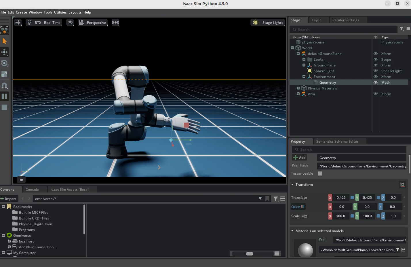
asset_path = '/home/mahaofei/Programs/01_MR+VLM+RL/Simulation/asset/isaac_sim/ur5e_hand/ur5e_hand.usd'
add_reference_to_stage(usd_path=asset_path, prim_path="/World/Arm")  # add robot to stage
arm = Articulation(prim_paths_expr="/World/Arm", name="my_arm")  # create an articulation object

# set the initial poses of the arm so they don't collide BEFORE the simulation starts
arm.set_world_poses(positions=np.array([[0.0, 1.0, 0.0]]) / get_stage_units())
# initialize the world
my_world.reset()

init_joint_positions = np.array([0.0, -np.pi/2, np.pi/2, 0.0, 0.0, 0.0, 0.0, 0.0, 0.0, 0.0, 0.0, 0.0, 0.0, 0.0, 0.0, 0.0, 0.0, 0.0])
arm.set_joint_positions([init_joint_positions])
arm_joint_positions = init_joint_positions

while True:
    # 机器人的关节位置每次变动一点,连续变动
    arm_joint_positions[:6] += 0.001
    arm.set_joint_positions([arm_joint_positions])
    if arm_joint_positions[0] >= np.pi/2:
        arm_joint_positions = init_joint_positions

    # step the simulation, both rendering and physics
    my_world.step(render=True)

simulation_app.close()
4.3 Common Python programs and explanations
(1) Typical code flow
Creating simulation_app must happen before any Isaac Sim imports, which launches the Isaac Sim simulation window.
# Start SimulationApp
from isaacsim import SimulationApp  # 第一行一定是导入SimulationApp

simulation_app = SimulationApp({"headless": False})  # 创建一个 SimulationApp 对象,参数是一个字典,headless: False 表示显示图形界面

import sys
import carb
import numpy as np
from isaacsim.core.api import World
from isaacsim.storage.native import get_assets_root_path

# 准备场景,获取NVIDIA官方asset路径
assets_root_path = get_assets_root_path()
if assets_root_path is None:
    carb.log_error("Could not find Isaac Sim assets folder")
    simulation_app.close()
    sys.exit()

# 创建世界,添加地面,添加相机视角
my_world = World(stage_units_in_meters=1.0)
my_world.scene.add_default_ground_plane()  # add ground plane
set_camera_view(
    eye=[5.0, 0.0, 1.5], target=[0.00, 0.00, 1.00], camera_prim_path="/OmniverseKit_Persp"
)  # set camera view

# 初始化world
arm.set_world_poses(positions=np.array([[0.0, 1.0, 0.0]]) / get_stage_units())
my_world.reset()

# some code

while True:
	# some code

	my_world.step(render=True)

simulation_app.close() # 关闭仿真
5. Importing URDF Models into Isaac Sim
(1) Open the URDF import extension
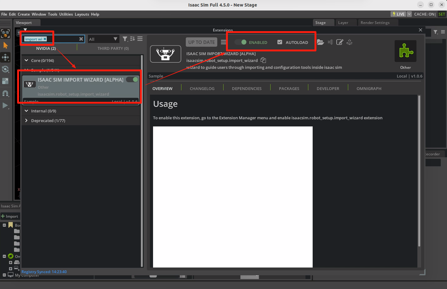
Click 【Windows -> Entensions】, search 【import wizard】, and open this extension. If you need to import models frequently, you can check Autoload so the extension starts automatically every time you launch IsaacSim.
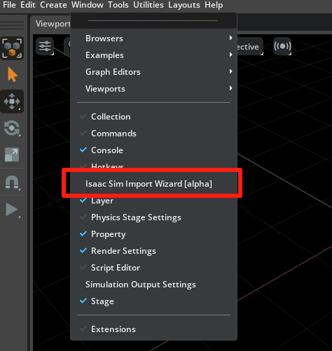
Then click 【Windows】. You should now see an additional option, 【Isaac Sim Wizard [alpha]】, which is the feature we need. Open it.
(2) Import a URDF model
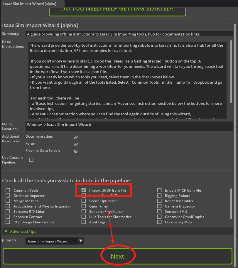
On the first page, check 【Import URDF from File】 at the bottom. You can also import from other model files here, such as MJCF files used by MuJoCo. Then click 【Next】.
On the next page, there is nothing to do; just click Next.
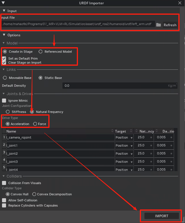
Then a URDF Importer window appears. Here, fill in or check the items marked in the figure below, including:
- URDF file location
- Create the file in the Stage, set it as Default Prim, and clear the current Stage on import
- Set the joint drive type to acceleration drive
(3) Save the USD file
The model is then imported, but it may be hard to see because there are no lights. That is normal.
Press 【Ctrl+S】 to save the model locally.
If you want to view the model, create a new Stage and drag the USD model into it to see the colored model.
Comments