Introduction to Using the Isaac Sim Simulation Environment
An introduction to the NVIDIA Isaac Sim simulation environment, covering installation, the GUI, and basic usage of Python programs.
40 posts
An introduction to the NVIDIA Isaac Sim simulation environment, covering installation, the GUI, and basic usage of Python programs.
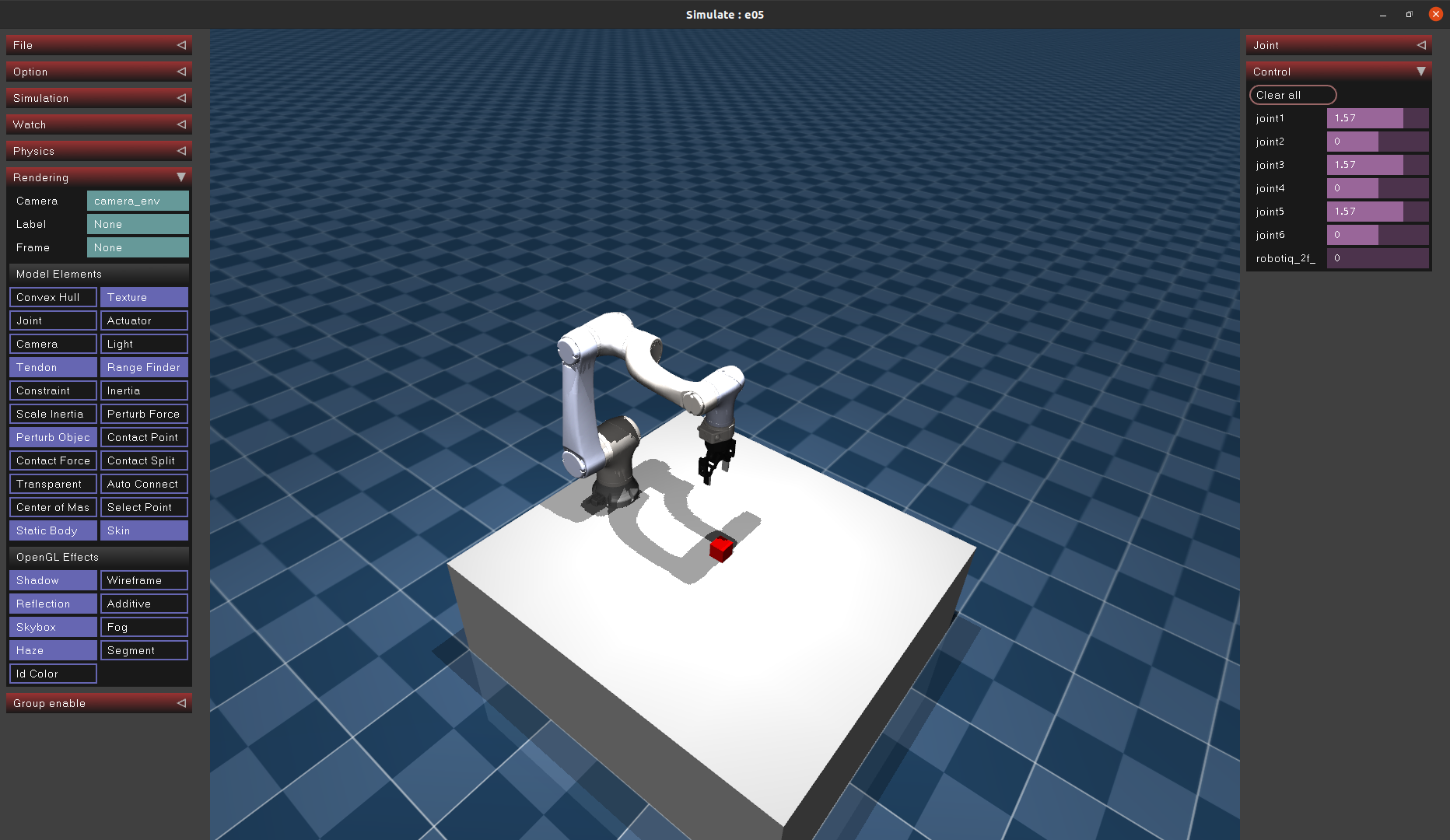
Import a custom robot model into MuJoCo to lay the groundwork for building simulation environments for future reinforcement learning.
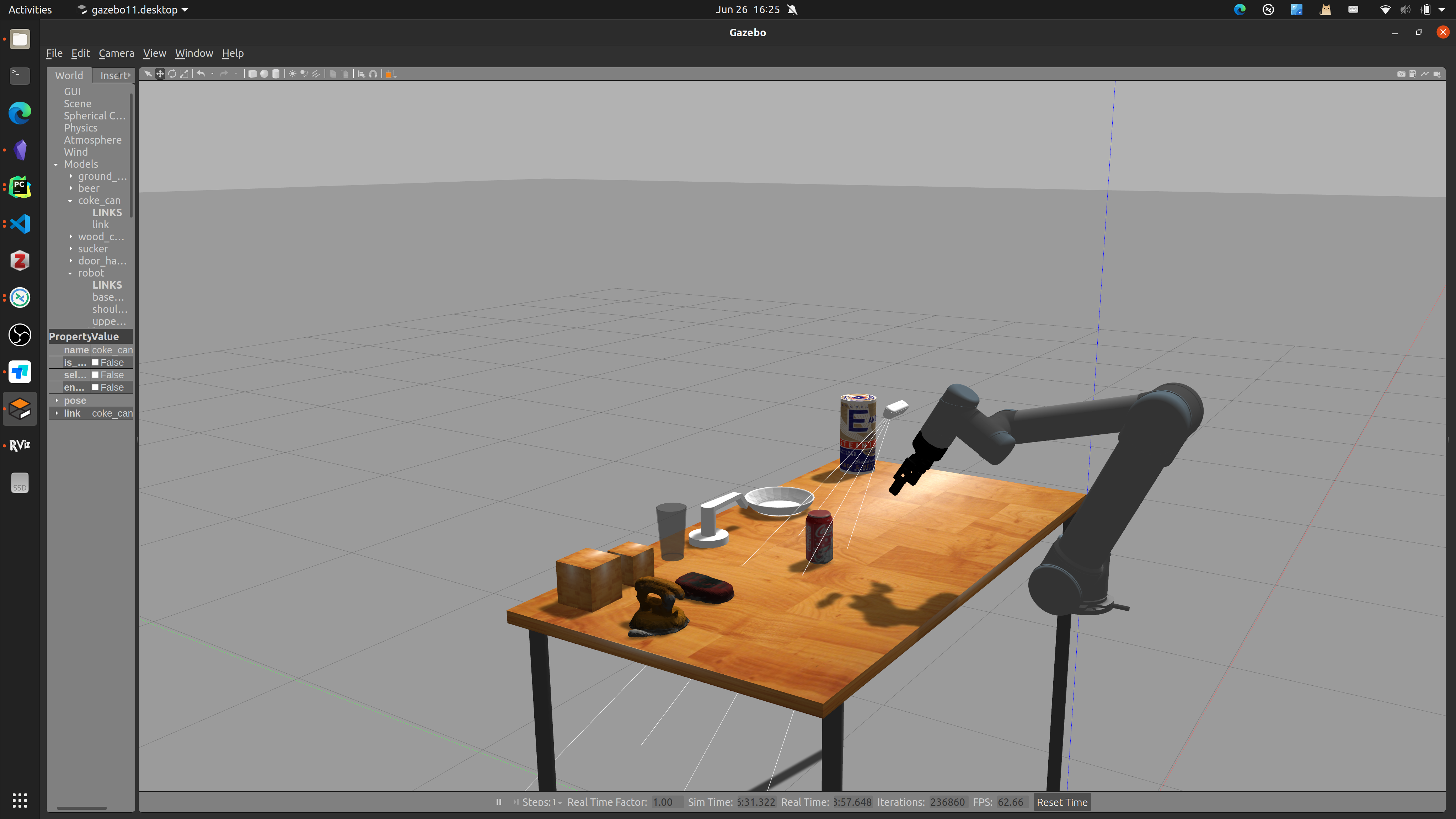
Build a 6D robotic arm simulation environment in Gazebo, add a camera, and implement a grasping simulation experiment.
Using the classic YOLO algorithm for instance segmentation
Reproducing the RGB Matters algorithm proposed by Shanghai Jiao Tong University.
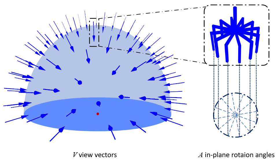
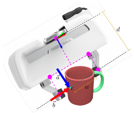
Reproducing Contact GraspNet, a grasp estimation algorithm proposed by NVIDIA
Algorithm reproduction
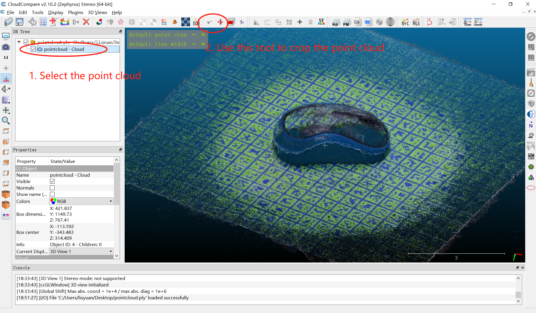
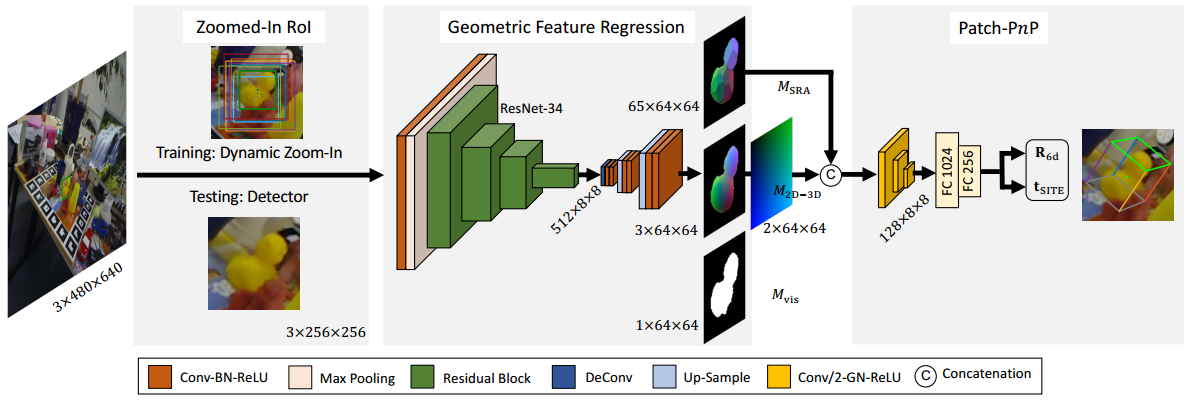
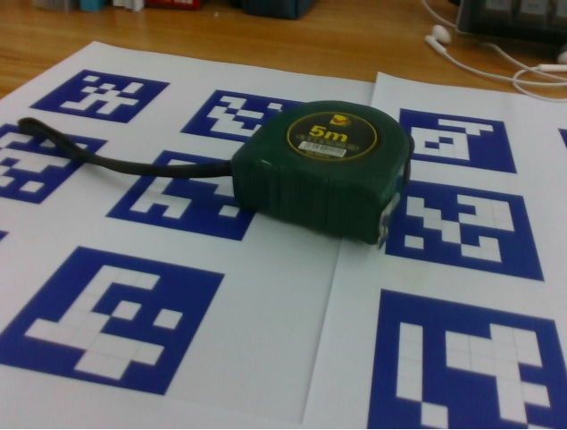
I am currently studying 6D pose estimation algorithms. The LINEMOD dataset is the most commonly used dataset in this field, but testing only on an existing dataset is not enough. Building a custom dataset is necessary for practical applications.
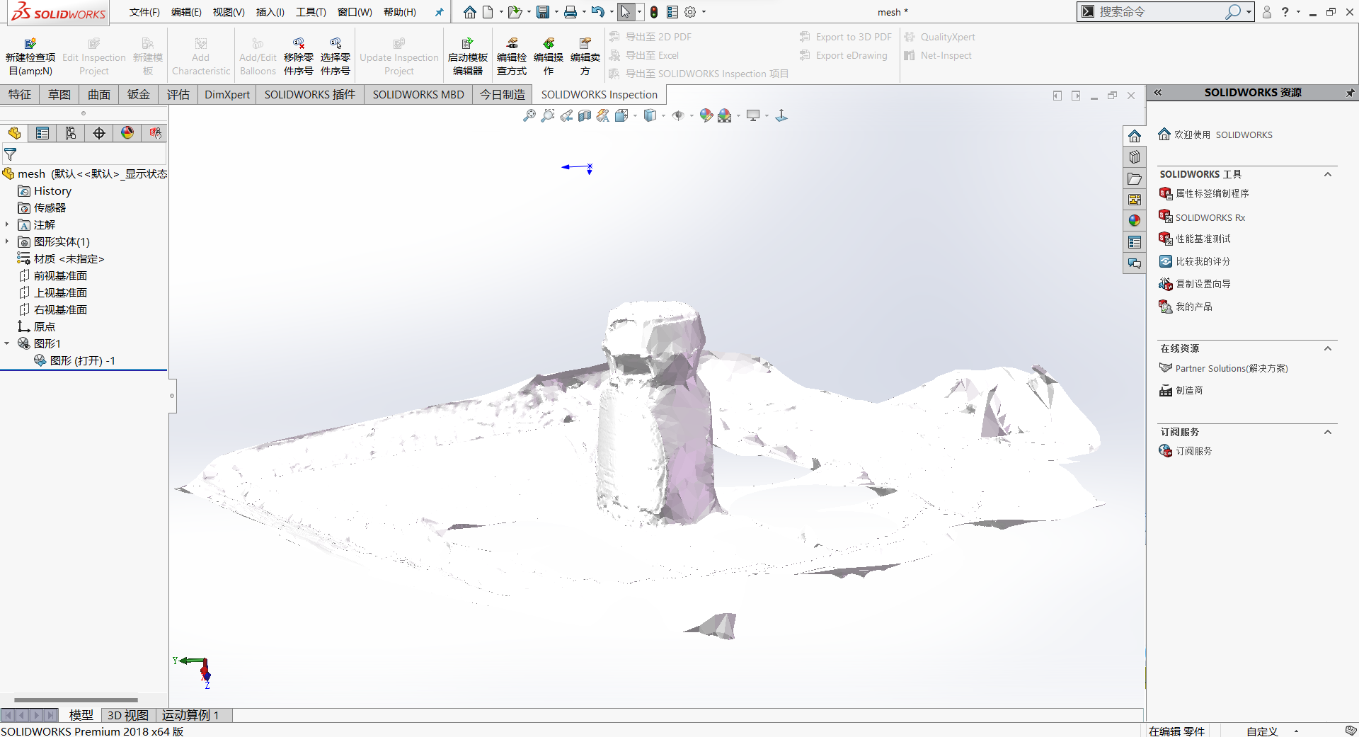
COLMAP is a general-purpose Structure-from-Motion (SfM) and Multi-View Stereo (MVS) tool with graphical and command-line interfaces. OpenMVS is one of the three-dimensional reconstruction frameworks that produces better reconstruction results, and it provides automated scripts.
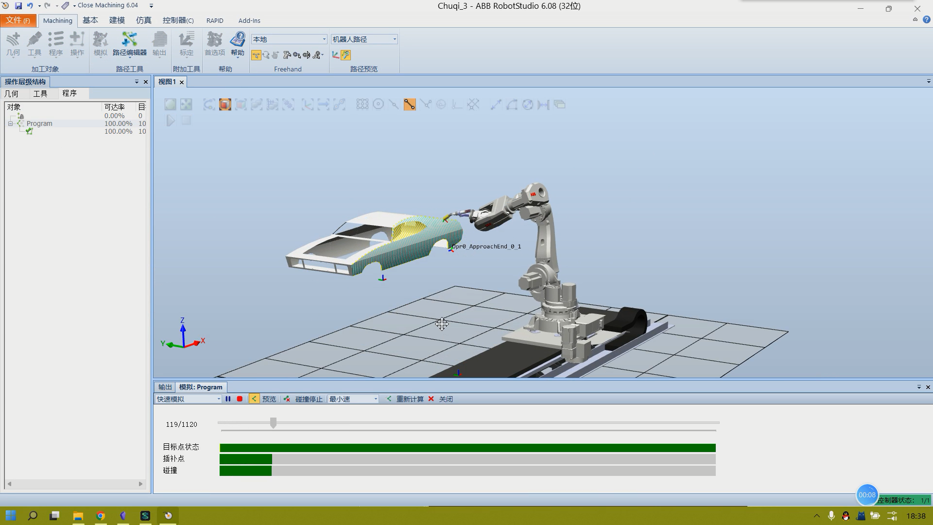
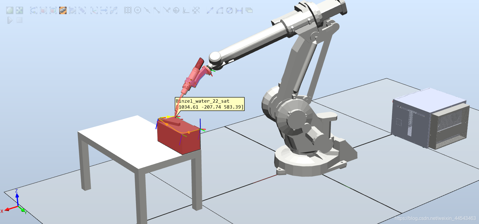
Import a CAD model with complex curved surfaces, such as a car body, into RobotStudio. Use RobotStudio for path planning to enable a robotic arm to paint the car body.
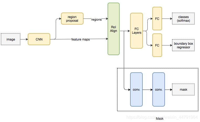
Mask R-CNN is a major 2017 work by Kaiming He. It performs instance segmentation alongside object detection and achieves excellent results.
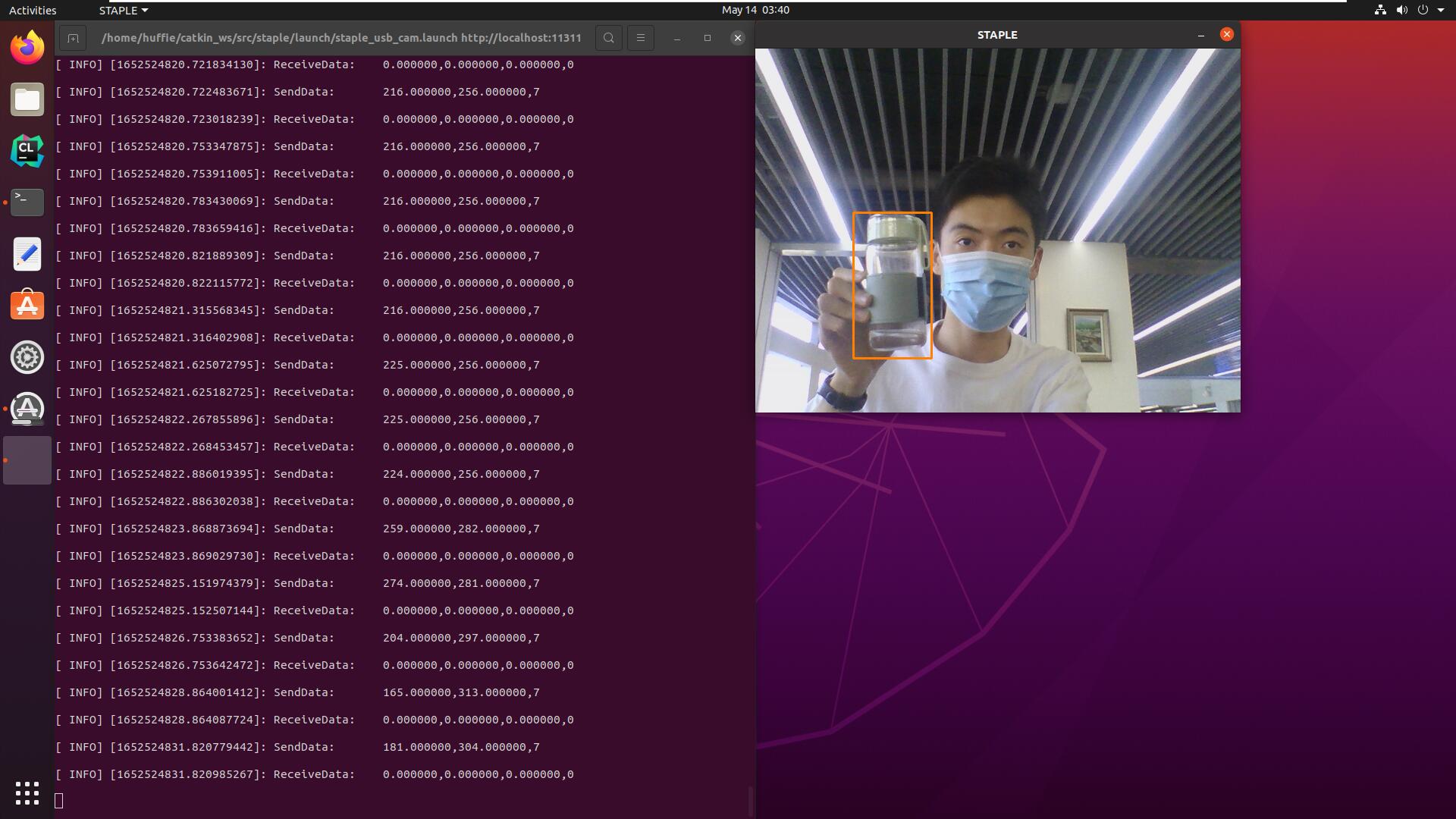
Implemented bidirectional serial communication over UART between a host PC running ROS Noetic and an STM32F1 development board.
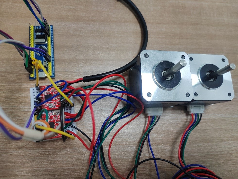
Driving a 42-series stepper motor with an A4988 chip, tested on the STM32F1 platform, with up to 16× microstepping.
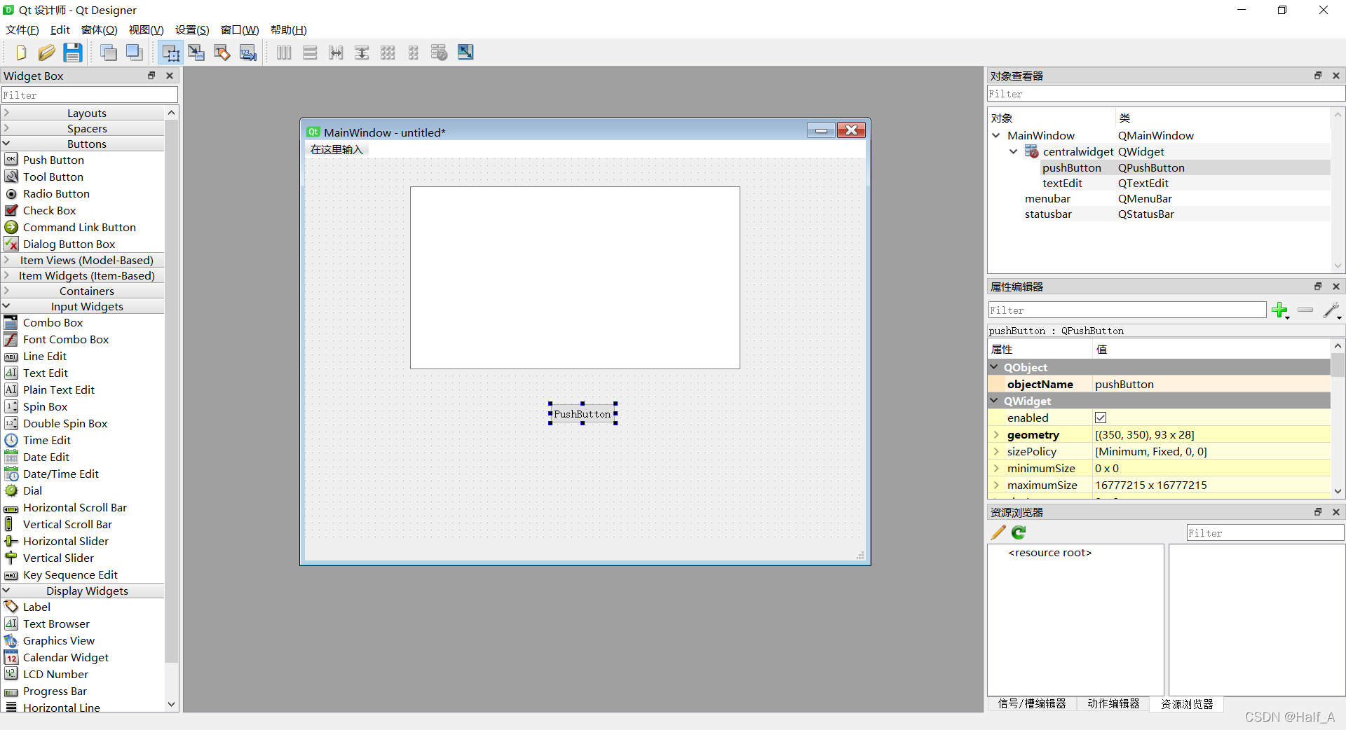
The lab recently needed to process many spreadsheets, so I built a Python tool to help. The program uses PyQt5 for the graphical interface. This post records the full workflow—from installing PyQt5, to designing the UI, to writing code that drives the widgets, and finally packaging the app as an exe.
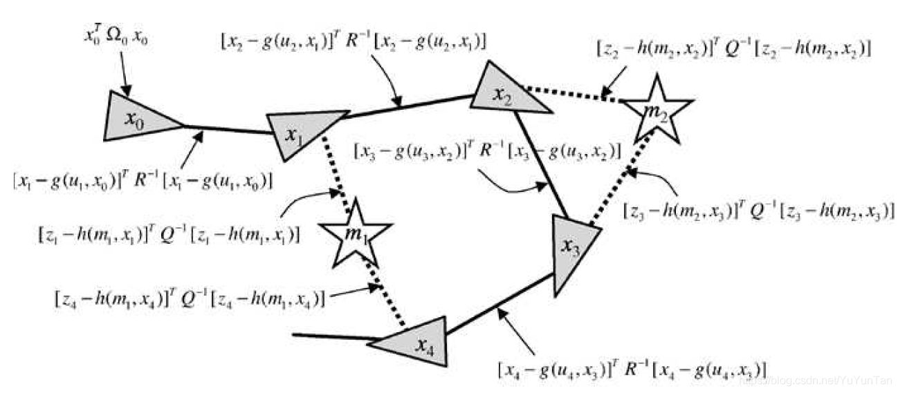
g2o (General Graph Optimization) is a graph optimization library that combines nonlinear optimization with graph theory. We can use g2o to solve any least-squares problem that can be represented as graph optimization.
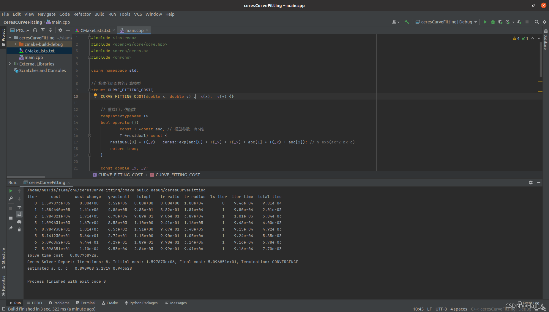
Ceres is a library for solving least-squares problems. We only need to define the problem to be optimized and let it perform the computation. Usage: 1. Define each parameter block. A parameter block is simply a vector, but it can also have a special structure such as a quaternion or Lie algebra……
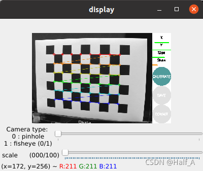
The purpose of camera calibration is to eliminate camera distortion. For details on how distortion occurs, see the previous article. The process of calibrating a USB camera in ROS can be broadly divided into several steps. ① Install the usb_camera driver package; ② run usb_cam to capture images from the USB camera; ③ download and print a checkerboard, then calibrate the camera.
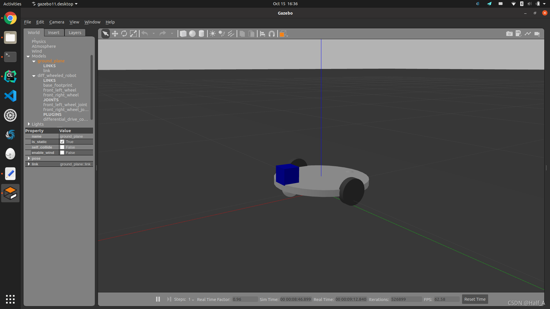
Use xacro description files to create a differential-drive robot model, simulate the model in Gazebo, then use the libgazebo_ros_diff_drive.so plugin to control the robot's motion, and finally implement keyboard control of the robot in the Gazebo environment.
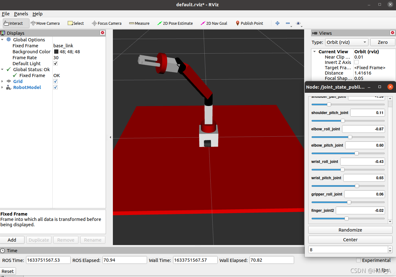
Why create a three-dimensional robot model? Robot simulation tools can help us identify critical errors in a design. Model simulation means that we create a robot model, so it does not necessarily look exactly like the real robot. However, because it is a simulation, the model must include all the characteristics of the real hardware.
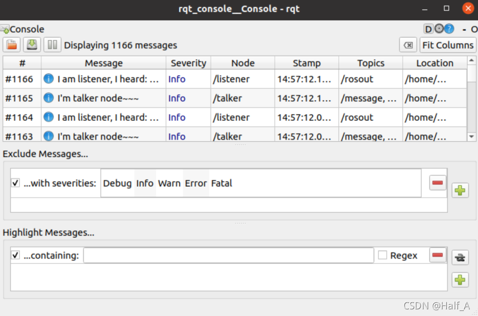
Starting with the creation of a workspace and package, this article explains the creation and compilation steps and provides a detailed summary of commonly used ROS commands. It then uses specific examples to explain in detail how to create nodes, services, launch files, and dynamic parameters, and demonstrates how they are used.
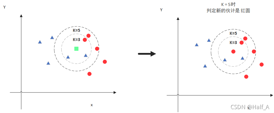
The KNN algorithm, or K-nearest neighbors algorithm, works by predicting the class of a new value x based on which class most of its K nearest neighbors belong to. The same idea applies to image recognition.
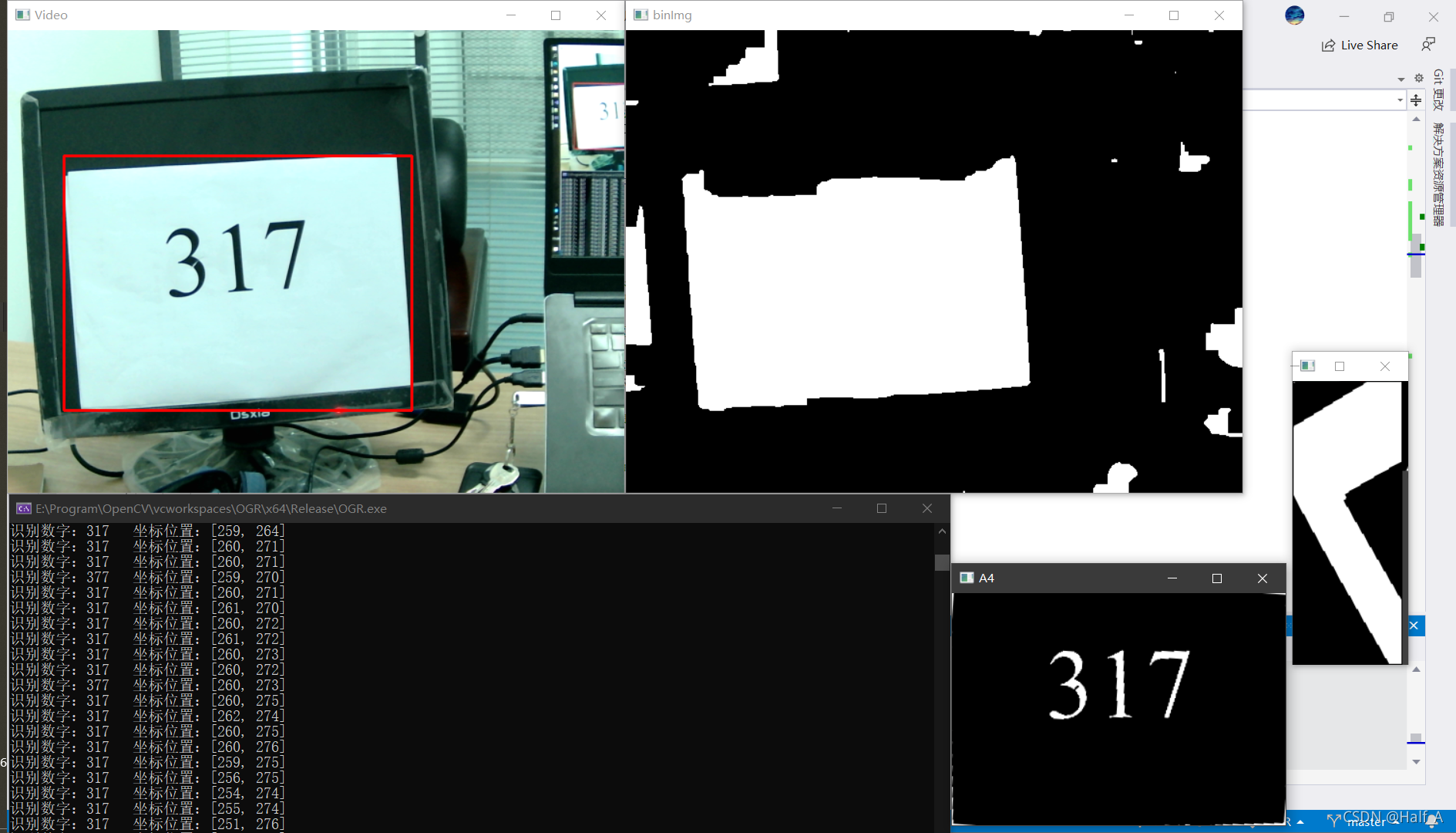
This article aims to recognize digits in camera images. Practical applications include license plate number recognition and recognizing printed digits on A4 paper in some competitions. Camera-based digit recognition consists of two steps: 1. Extract the ROI from the image, such as the rectangular license plate area or the A4 paper image. 2. Recognize digits in the ROI. Digit recognition is relatively straightforward, so this article first introduces its methods and principles.
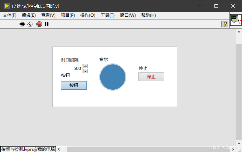
State machines are the most widely used design pattern in engineering applications. With a state machine, we can easily implement decisions and branches from program flowcharts. A LabVIEW state machine consists of a While loop, a case structure, and a shift register.
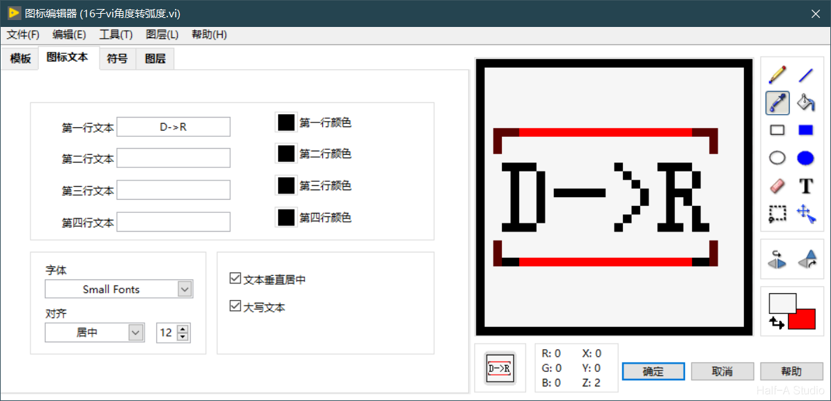
An important concept in programming is modularity, which means dividing a program into several blocks so that modifying one block does not affect the others. In LabVIEW, we use subVIs to implement modular programming.
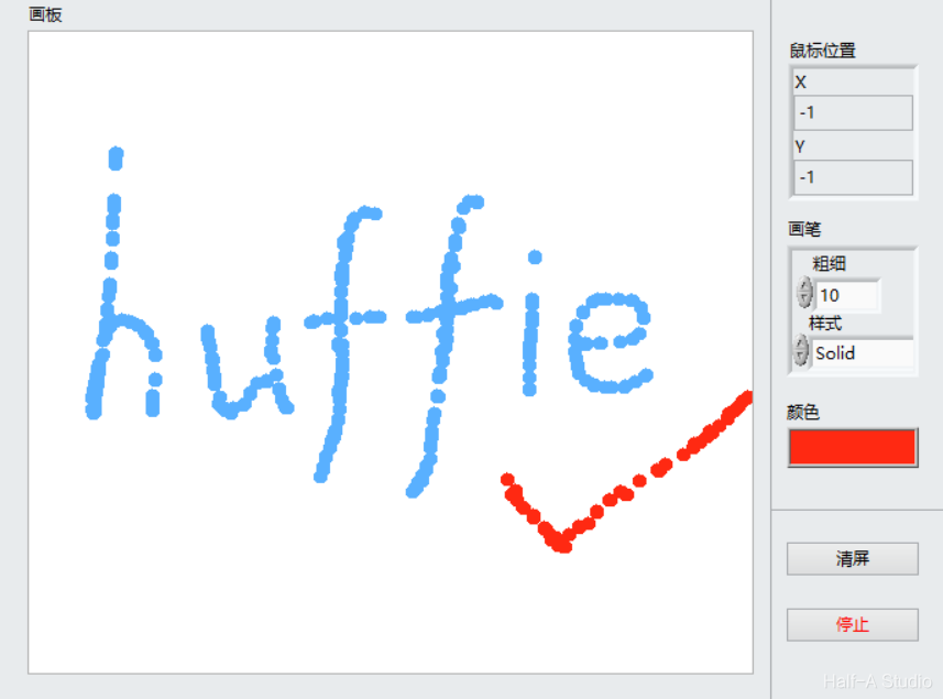
The two-dimensional Picture control provides pixel-level control and can create almost any graphical object. To display an image in a two-dimensional Picture control, you must write an image to the control programmatically. You can draw with the Picture Functions VIs.
A shift register passes the value generated in the previous loop iteration to the next iteration. Shift registers appear as pairs of terminals located at corresponding positions on the borders on opposite sides of a loop. A shift register must be initialized; that is, you must set the value that it passes to the first loop iteration.
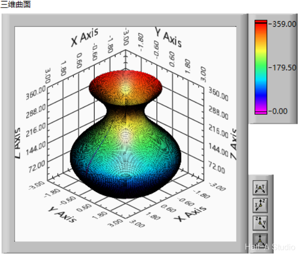
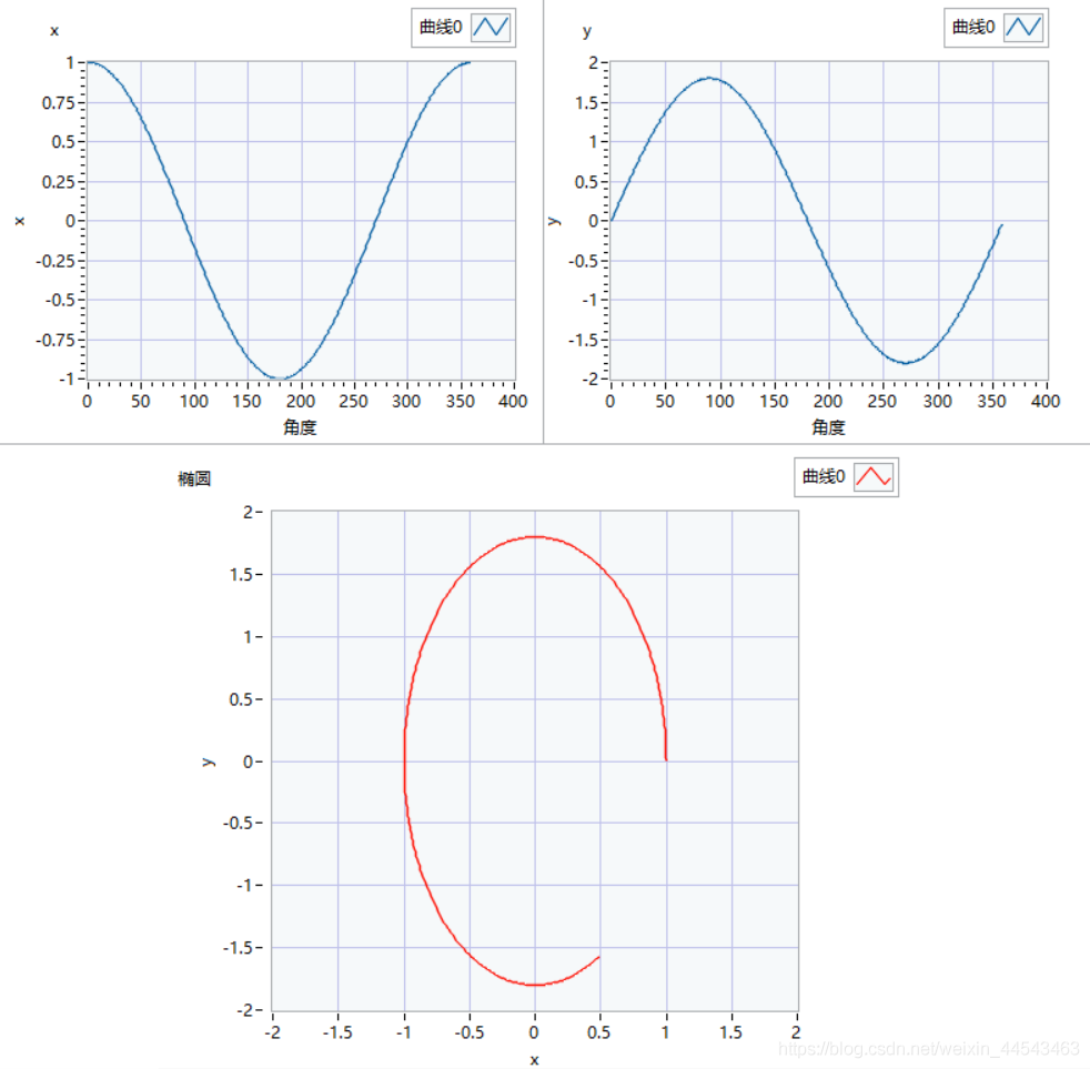
Generating a surface of revolution such as a vase essentially involves sweeping a profile along a guide curve. For a vase, the method is to sweep a circle along a curve. The circle is generated as follows: the total number of loop iterations is 360, corresponding to 360 degrees, while i represents each angle from 0~360.
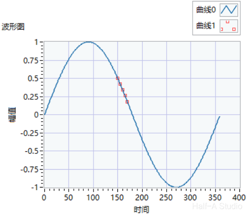
A for loop runs for a fixed number of iterations and also has a conditional terminal that can terminate a while loop early, equivalent to the break statement in C. For loops are closely tied to array operations, and their most important function is processing array data.
The components used include a simulated power supply, a transformer, a bridge rectifier, a non-polarized capacitor, an electrolytic capacitor, and a three-terminal voltage regulator IC. The wiring method is shown in the figure.
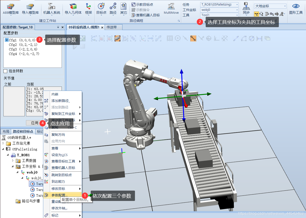
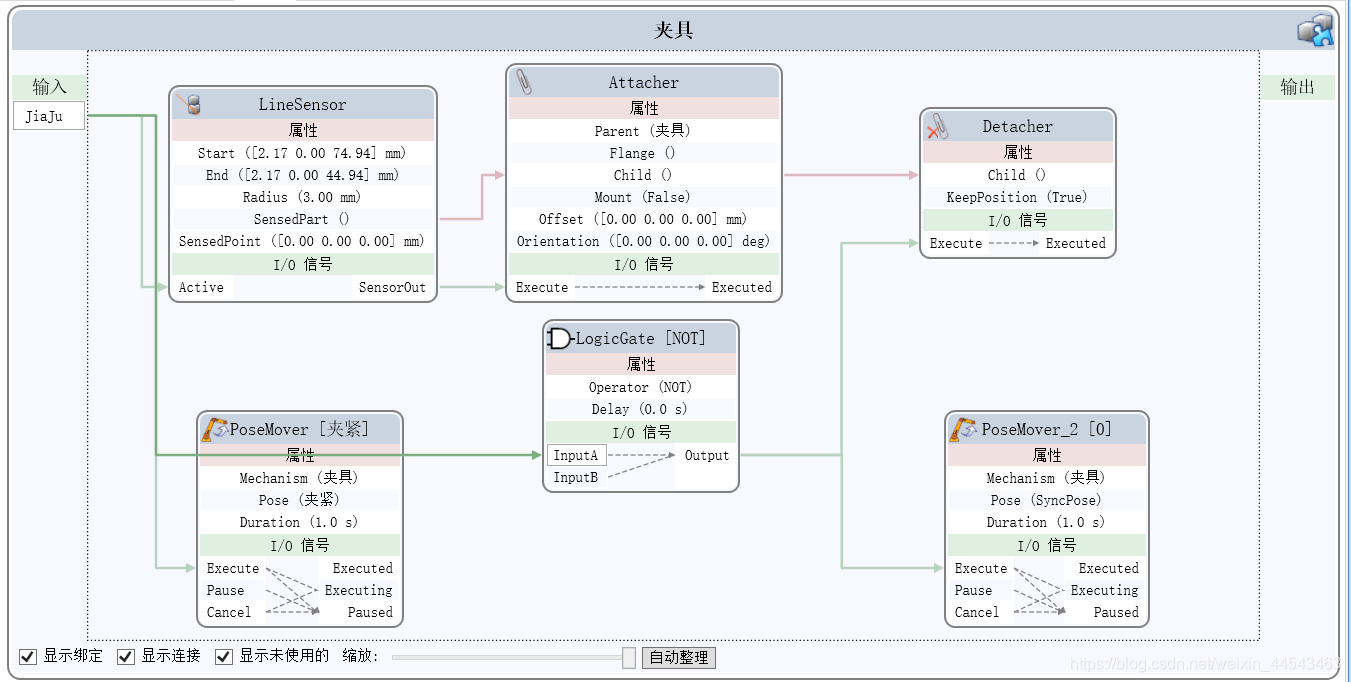
First, import an IRB2600 robot and move the gripper's local coordinate origin to the center of its top surface (where it connects to the flange). Align the local coordinates of the gripper Smart Component with the coordinates of the robot's end flange...
If you have a gripper model created with other modeling software such as SolidWorks, you can import it into RobotStudio. Here, a simple model is created, mainly to demonstrate the process of creating a dynamic gripper.
Click Create Collision Detection to create a collision check. Once created, ObjectA and ObjectB are the two groups to be checked. If objects in the two groups collide, their colors will change.
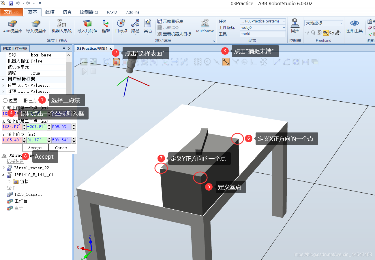
This article covers the process of creating a robot path after the mechanical model and robot system have already been created. The project files have been uploaded to a cloud drive, including the initial project file (03Practice_init.rspag), the completed project file (03Practice.rspag), and model files.
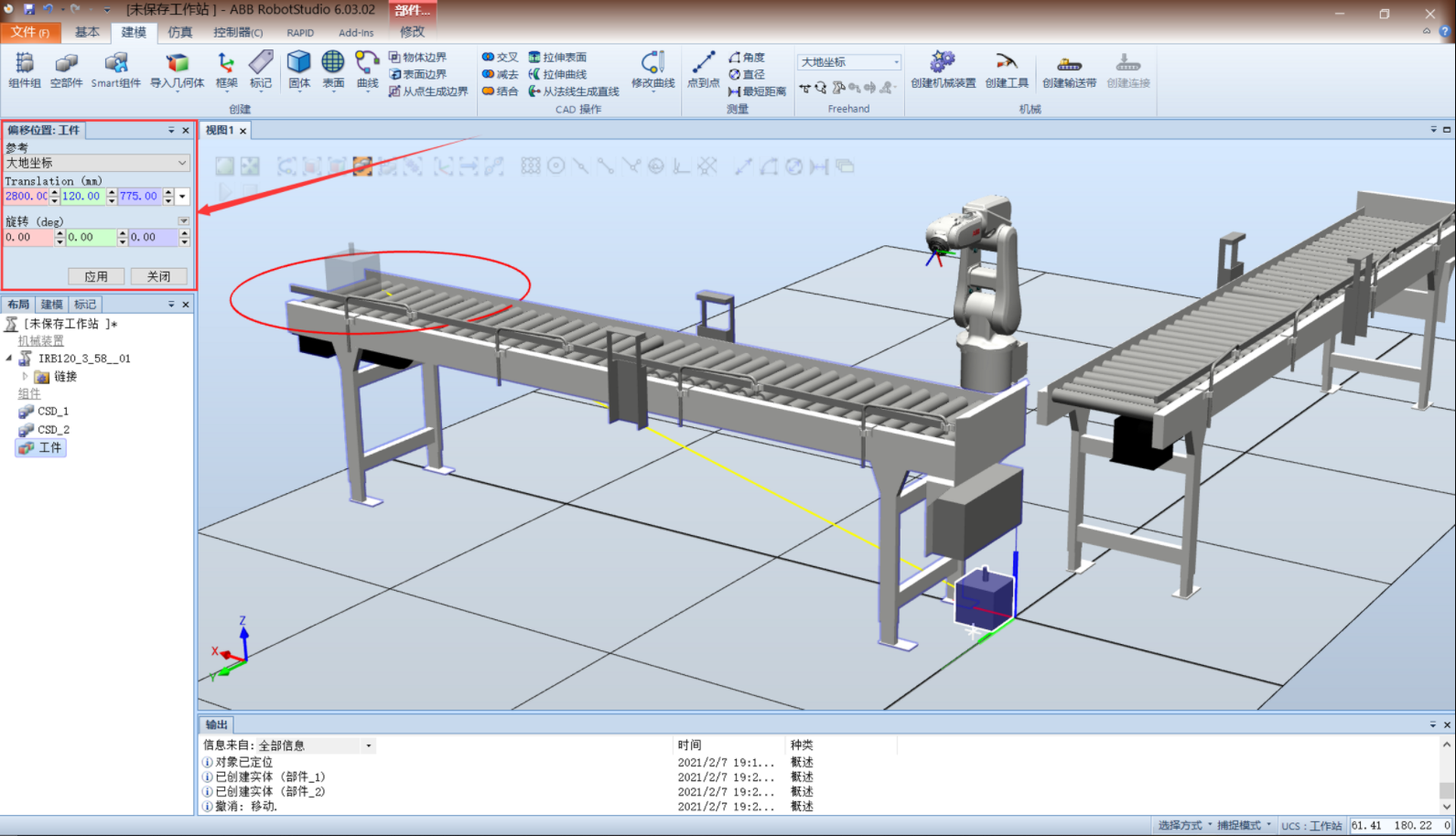
Start by building the mechanical structure of the system. Import two conveyors, rotate the second conveyor 90° about the z-axis, then offset it -3200mm along the y-axis. Import the IRB120 robot and move it to a suitable position. Create a workpiece model...
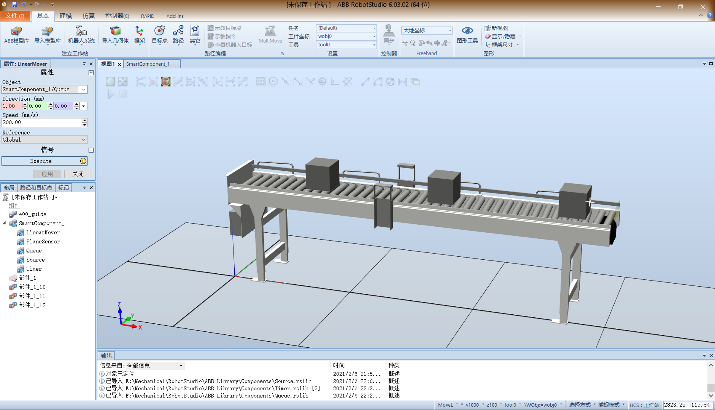
Create a new station and import a conveyor from Equipment. Create a cube to serve as the object carried by the conveyor. Drag the small cube onto the conveyor at the desired position, using Snap and Set Position to position it precisely...
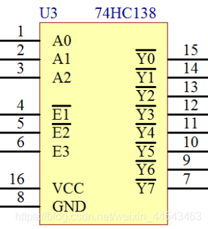
When designing MCU circuits, the number of MCU I/O pins is limited and sometimes cannot meet our design requirements. To control more devices, we need peripheral digital chips for pin expansion. A common choice is the 74HC138, also called a three-to-eight (38) decoder.
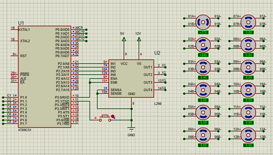
The CD4066 is a quad bilateral analog switch. Connect the four inputs of the CD4066 to the L298N outputs and the CD4066 outputs to the stepper motor's A+, A-, B+, and B- terminals. Tie all four control pins to one MCU pin so a single pin can switch all four switches on the CD4066 together, enabling stepper motor selection.
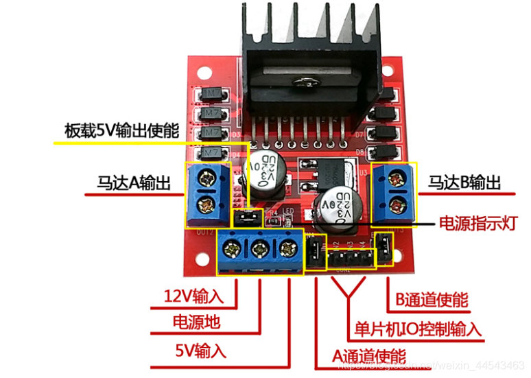
A microcontroller cannot drive a stepper motor directly, so an L298N is needed as the driver. This article introduces some L298N parameters, along with the drive principles and methods for a two-phase four-wire stepper motor. A simulation experiment is also performed in Proteus based on the drive principles described.
This experiment uses an ESP8266 NodeMCU. The firmware flashed is the official NodeMCU firmware. Open the official ESP8266Flasher, select the NodeMCU firmware in the Config tab, and set the flash address to 0x00000.