Contents
- Zero. Background Knowledge
- 1.1 URDF
- 1.2 MoveIt Control
- I. Setting Up the Experiment Environment
- 1.0 Install ROS
- 1.1 Convert a SolidWorks Robot Model to URDF
- 1.2 View the Model in ROS
- 1.3 Add the Robotiq 2F-85 Gripper
- 1.4 Create MoveIt Drivers
- II. Setting Up the Experiment Environment
- 2.1 Install the UR Robot and Drivers
- 2.2 Simple Tests
- 2.3 Import Custom Objects
Zero. Background Knowledge
1.1 URDF
URDF is the robot model description format in ROS. It covers aspects such as the robot’s appearance, physical properties, and joint types.
<robot>: the top-level tag<link>: describes a rigid body’s appearance, collision geometry, color, inertia matrix, and related properties<joint>: describes the relationship between two links. There are 6 types; the most commonly used isrevolute, a rotational joint with position limits
xacro models can package part of a URDF into a “class” and call it from other models.
A package generally includes the following four parts:
cfg: configuration fileslaunch: loads the URDF model and displays it in RVizmeshes: visual models used by the URDFurdf: URDF model definitions
1.2 MoveIt Control
(1) Overview of MoveIt!
- Kinematics computation
- Motion planning
- Collision detection
The most important node is move_group. Its input can come from data in RViz or from point clouds and depth images. Path planning generally uses the OMPL library, and collision detection uses the FCL library. It finally sends the trajectory to the robotic arm for execution.
I. Setting Up the Experiment Environment
1.0 Install ROS
See the Ubuntu20.04 Installing ROS Noetic article.
1.1 Convert a SolidWorks Robot Model to URDF
This simulation experiment uses the Han’s E05 robot and the Robotiq 2F-85 gripper.
For this part, refer to this video.
First, download the robot model and convert it to URDF.
(1) Install the sw_urdf_exporter plugin
Download the sw_urdf_exporter plugin: http://wiki.ros.org/sw_urdf_exporter. Downloading the latest version is enough; the latest version also supports older SolidWorks versions.
Close SolidWorks.
Run sw2urdfSetup.exe and install it as prompted.
(2) Add reference axes (rotation axes) to the robot
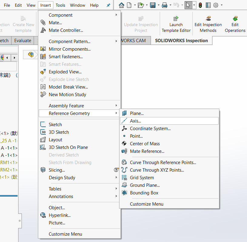
Select six cylindrical faces in turn to define the directions of the six rotation axes.

(3) Export URDF
Check whether Tools → at the bottom, File → Export as URDF is available. If it is, open it directly. If not, open Tools → Add-Ins and enable the two checkboxes for the Sw2URDF plugin at the bottom.
Follow the process below to create base_link and link1-6.

Then click Preview and Export.
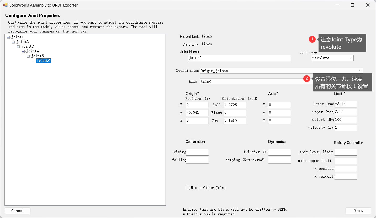
Then click Next and Export URDF and Mesh. It will save the URDF model as a package to the location you specify.
After creation, be sure to check whether the last coordinate frame is at the center of the flange at the robot end, because adding the gripper later requires this frame. If it is not, adjust the frame position manually and regenerate the URDF.
1.2 View the Model in ROS
Create a workspace.
mkdir -p catkin_robot/src
cd catkin_robot/src
catkin_init_workspace
Copy the package into the src directory.
Build the workspace.
cd ../..
catkin_make
Run the test program.
source devel/setup.bash
roslaunch e05 display.launch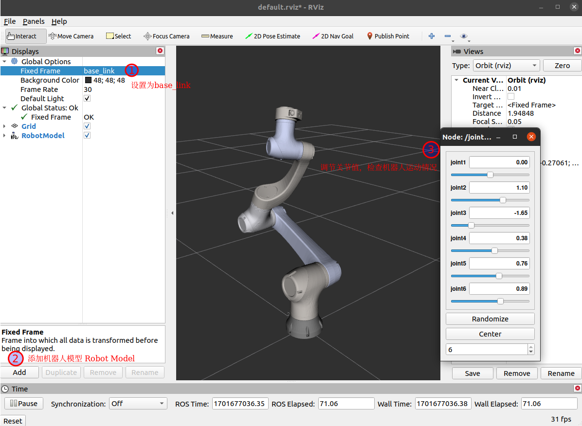
1.3 Add the Robotiq 2F-85 Gripper
(1) Prepare the gripper environment
Go to the src directory of the workspace.
cd src
git clone https://github.com/ros-industrial/robotiq.git
In the urdf folder of your robotic arm package, create a new file named common.gazebo.xacro.
cd src/e05/urdf
gedit common.gazebo.xacro
Add the following content.
<?xml version="1.0"?>
<robot xmlns:xacro="http://wiki.ros.org/xacro">

  <gazebo>
    <plugin name="ros_control" filename="libgazebo_ros_control.so">
    </plugin>
  </gazebo>

</robot>
For convenience, I added to the end of e05.urdf an ee_link.
<link name="ee_link">
  <visual>
    <origin xyz="0 0 0" rpy="0 0 0" />
    <geometry>
      <sphere radius="0.01" /> <!-- You can use any simple geometry like a sphere for visualization -->
    </geometry>
    <material name="">
      <color rgba="1 0 0 1" /> <!-- Choose a color for visualization -->
    </material>
  </visual>
</link>

<joint name="ee_joint" type="fixed">
  <origin xyz="0 0 0" rpy="0 0 0" />
  <parent link="link6" />
  <child link="ee_link" />
</joint>
Create another xacro file (for example, if your robotic arm package is named e05).
gedit e05.xacroAdd the content below. Note: modify your robotic arm package name in the Gazebo支持 and E05机械臂 sections, and change the parent on the first line of the 夹爪与机械臂连接 section. I connected it to link6, the end link.
<?xml version="1.0"?>
<robot xmlns:xacro="http://www.ros.org/wiki/xacro" name="e05">
    <xacro:arg name="transmission_hw_interface" default="hardware_interface/PositionJointInterface"/>

    <!-- E05机械臂 -->
    <xacro:include filename="$(find e05)/urdf/e05.urdf" />


    <!-- Gazebo 支持 -->
    <xacro:include filename="$(find e05)/urdf/common.gazebo.xacro" />
    <!-- 加载gazebo中需要使用的模型 -->
    <!-- macros for transmission -->
    <xacro:macro name="transmission_block" params="joint_name">
	  <transmission name="tran1">
	    <type>transmission_interface/SimpleTransmission</type>
	    <joint name="${joint_name}">
	      <hardwareInterface>hardware_interface/PositionJointInterface</hardwareInterface>
	    </joint>
	    <actuator name="motor1">
	      <hardwareInterface>hardware_interface/PositionJointInterface</hardwareInterface>
	      <mechanicalReduction>1</mechanicalReduction>
	    </actuator>
	  </transmission>
   </xacro:macro>
    <!-- Transmissions for ros control -->
    <xacro:transmission_block joint_name="joint1"/>
    <xacro:transmission_block joint_name="joint2"/>
    <xacro:transmission_block joint_name="joint3"/>
    <xacro:transmission_block joint_name="joint4"/>
    <xacro:transmission_block joint_name="joint5"/>
    <xacro:transmission_block joint_name="joint6"/>
    <!-- <xacro:include filename="$(find e05)/urdf/e05.gazebo.xacro" /> -->


    <!-- 机器人固定在世界坐标系下 -->
    <link name="world" />
    <joint name="world_joint" type="fixed">
        <parent link="world" />
        <child link = "base_link" />
        <origin xyz="0.0 0.0 0" rpy="0.0 0.0 0.0" />
    </joint>

    <!-- Robotiq 2F-85夹爪 -->
    <xacro:include filename="$(find robotiq_2f_85_gripper_visualization)/urdf/robotiq_arg2f_85_macro.xacro" />
    <xacro:include filename="$(find robotiq_85_description)/urdf/robotiq_85_gripper.urdf.xacro" />
    <gazebo>
        <plugin name="gazebo_grasp_fix" filename="libgazebo_grasp_fix.so">
            <arm>
                <!-- <arm_name>应该是一个单独的名字,不能和别的任何关节同名 -->
                <arm_name>ur5_gripper</arm_name>
                <!-- <palm_link>是和手指相连的关节 -->
                <palm_link>link6</palm_link>
                <!-- <gripper_link>是会检测碰撞的关节 -->
                <gripper_link>gripper_finger1_finger_tip_link</gripper_link>
                <gripper_link>gripper_finger2_finger_tip_link</gripper_link>
                <gripper_link>gripper_finger2_knuckle_link</gripper_link>
                <gripper_link>gripper_finger1_knuckle_link</gripper_link>
                <gripper_link>gripper_finger1_inner_knuckle_link</gripper_link>
                <gripper_link>gripper_finger2_inner_knuckle_link</gripper_link>
            </arm>
            <forces_angle_tolerance>150</forces_angle_tolerance>
            <!-- 检测频率 -->
            <update_rate>130</update_rate>
            <!-- 检测为抓取状态的接触次数阈值 -->
            <grip_count_threshold>2</grip_count_threshold>
            <max_grip_count>8</max_grip_count>
            <!-- 释放时的容忍度,超过这个就会把物体放下。数值越大,需要把夹爪打开更大才能释放物体 -->
            <release_tolerance>0.005</release_tolerance>
            <disable_collisions_on_attach>true</disable_collisions_on_attach>
            <contact_topic>__default_topic__</contact_topic>
        </plugin>
    </gazebo>


    <!-- 将夹爪实例化,并设置夹爪和机械臂的关系(连接在tool0上) -->
    <xacro:robotiq_85_gripper prefix="" parent="ee_link" >
        <origin xyz="0 0 0" rpy="0 ${-pi/2} 0"/>
    </xacro:robotiq_85_gripper>

    <!-- 相机实例化,然后设置仿真位置 -->
    <!-- <xacro:include filename="$(find realsense_ros_gazebo)/xacro/depthcam.xacro"/>
    <xacro:realsense_d435 sensor_name="d435" parent_link="tool0" rate="10">
        <origin rpy="0 ${-pi/2} 0 " xyz="-0.1 0 0"/>
    </xacro:realsense_d435> -->

</robot>
Modify the original launch file. For convenience later, I renamed the original display.launch to display_e05_with_gripper.launch. The main change is this line: <param name="robot_description" command="$(find xacro)/xacro '$(find e05)/urdf/e05.xacro'" /> — update it to use the xacro file you just created.
<launch>
  <arg name="model" />
  <!-- <param name="robot_description" textfile="$(find e05)/urdf/e05.xacro" /> -->
  <param name="robot_description" command="$(find xacro)/xacro '$(find e05)/urdf/e05.xacro'" />
  <node name="joint_state_publisher_gui" pkg="joint_state_publisher_gui" type="joint_state_publisher_gui" />
  <node name="robot_state_publisher" pkg="robot_state_publisher" type="robot_state_publisher" />
  <node name="rviz" pkg="rviz" type="rviz" args="-d $(find e05)/urdf.rviz" />
</launch>
(2) View the robot in RViz
cd catkin_motion
catkin_make
source devel/setup.bash
roslaunch e05 display_e05_with_gripper.launch
Click Add in the lower-left corner and add the RobotModel.
Select base_link for Fixed Frame on the left to display the robot.
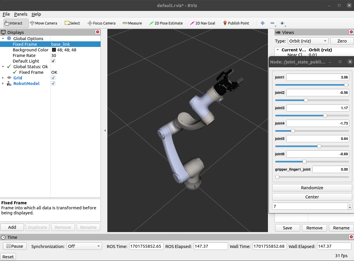
(3) View the robot in Gazebo
Create a gazebo_e05_with_gripper.launch file with content similar to the following.
<launch>
  <arg name="gui" default="true" doc="Starts gazebo gui" />
  <arg name="paused" default="false" doc="Starts gazebo in paused mode" />

  <!-- 启动仿真环境 后续有环境修改,可以替换此处的worlds/empty.world,改为例如"$(find ur_gazebo)/worlds/table_custom.world" -->
  <include file="$(find gazebo_ros)/launch/empty_world.launch">
    <arg name="world_name" default="$(find gazebo_ros)/launch/empty_world.world"/>
    <arg name="paused" value="$(arg paused)"/>
    <arg name="gui" value="$(arg gui)"/>
  </include>

  <!-- 加载TF -->
  <node name="tf_footprint_base" pkg="tf" type="static_transform_publisher" args="0 0 0 0 0 0 base_link base_footprint 40" />

  <!-- 启动机器人 -->
  <include file="$(find e05)/launch/display_e05_with_gripper.launch" />

  <!-- 将 robot_description 发送到 gazebo 中生成机器人 -->
  <!-- <node name="spawn_model" pkg="gazebo_ros" type="spawn_model" args="-file $(find e05)/urdf/e05.urdf -urdf -model e05" output="screen" /> -->
  <node name="spawn_gazebo_model" pkg="gazebo_ros" type="spawn_model" args="-urdf -param robot_description -model robot -z 0" respawn="false" output="screen" />

  <node name="fake_joint_calibration" pkg="rostopic" type="rostopic" args="pub /calibrated std_msgs/Bool true"/>

</launch>
Launch this launch file and you should see the robot in Gazebo.

1.4 Create MoveIt Drivers
For this part, refer to this article.
Install moveit.
sudo apt install ros-noetic-moveit
sudo apt install ros-noetic-object-recognition-msgs ros-noetic-soem* ros-noetic-socketcan-*
sudo apt install ros-noetic-moveit*
Start the MoveIt Setup Assistant.
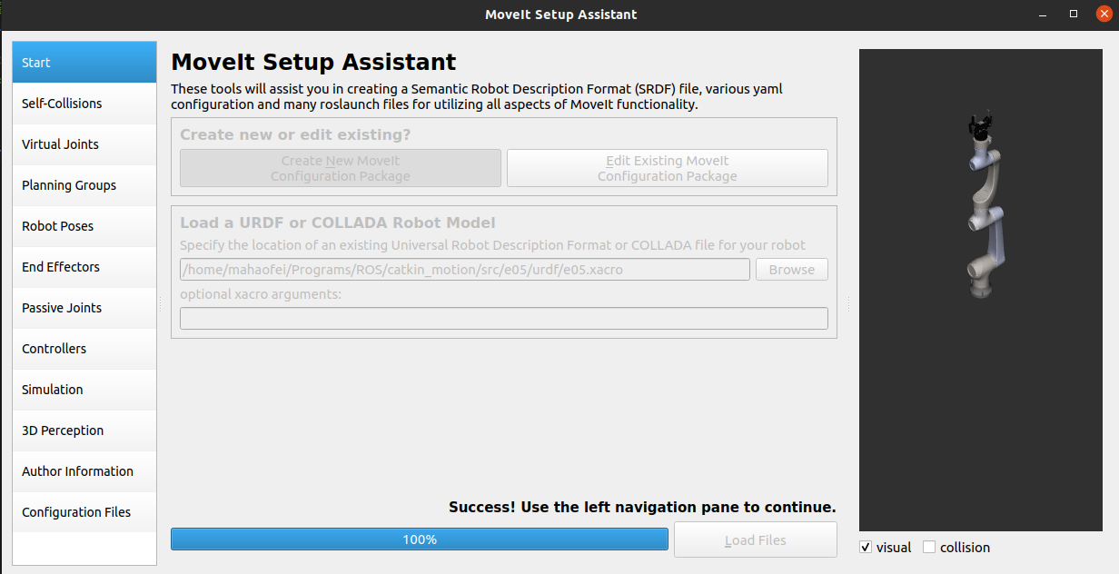
rosrun moveit_setup_assistant moveit_setup_assistantSelect Create New Moveit Configuration Package, choose your e05.xacro file, and click Load Files.
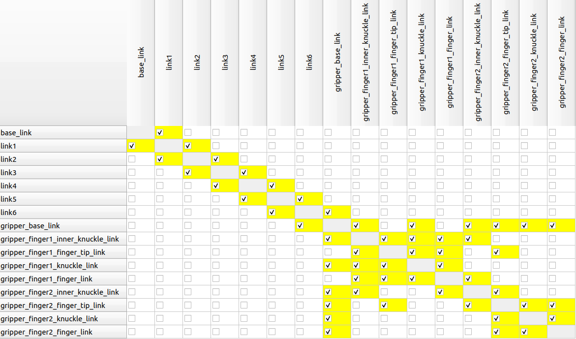
The second item on the left, Self-Collisions, checks collisions. Be sure to enable every pair that could collide; otherwise errors will occur later.
The third item, Virtual Joints, is generally not needed.
The fourth item, Planning Groups, is the most important. We need to configure the robotic arm and the end-effector gripper separately. Click Add Group.
Robotic arm:
- For Group Name, manipulator is usually fine
- For the kinematics solver, choose kdl
- For the path planning algorithm, the default RRT Star is fine
- Click
Add Kin. Chain, set Baselink to base_link, and set Tiplink to ee_link
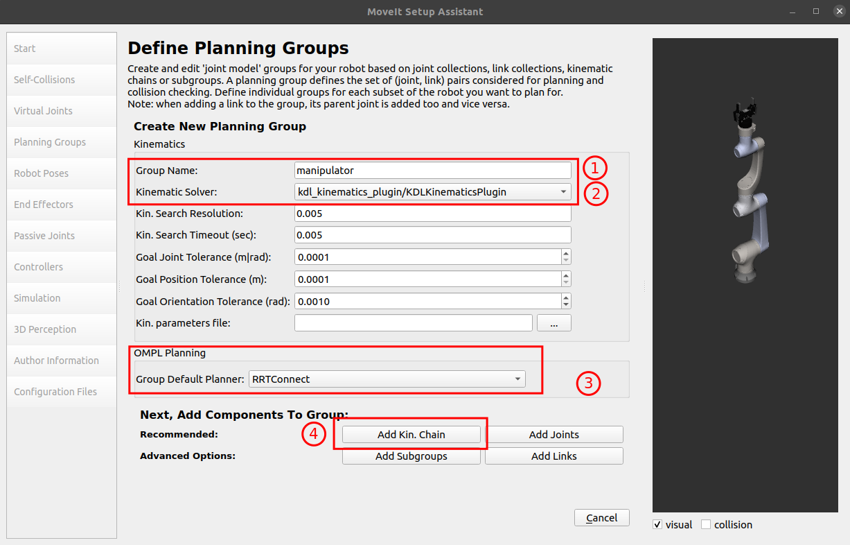
For the end-effector gripper, set Group Name to gripper; nothing else needs to be selected.
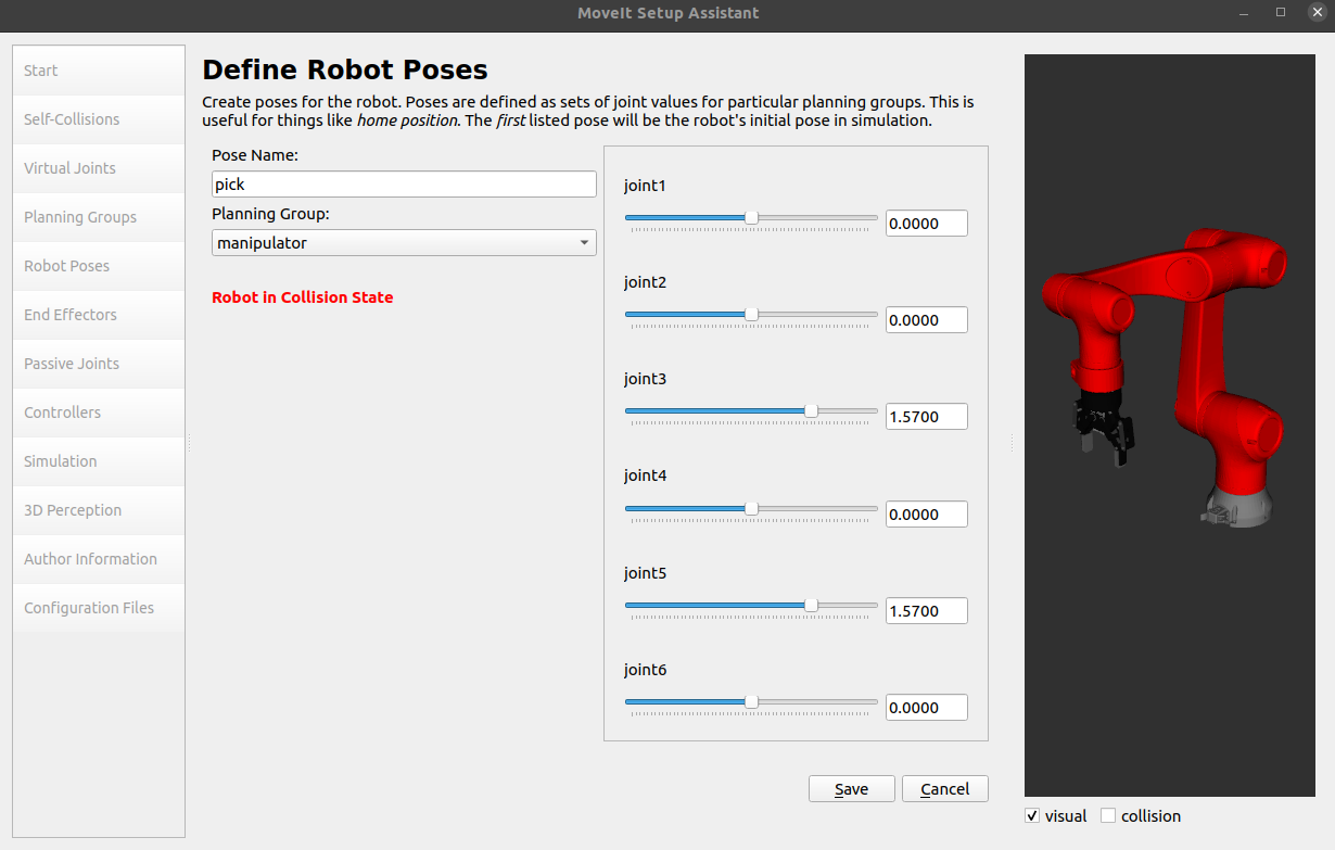
The fifth item, Robot Poses, can add commonly used poses so you can quickly move the robot to them, for example:
- up: robot initial upright pose
- pick: robot ready to grasp
- open: gripper open
- close: gripper closed
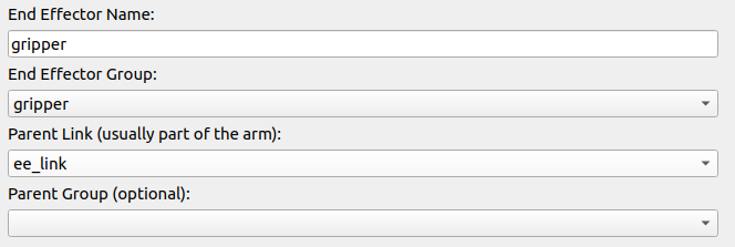
The sixth item, End Effectors, can be configured as shown below.
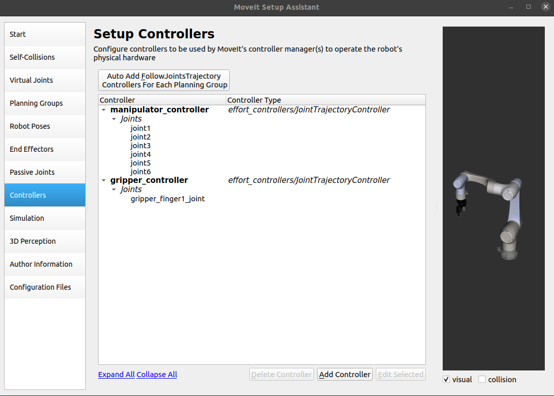
Click Controllers, then click Auto Generate in the upper-left corner.
Click the second-to-last item, Author Information, and fill in a name and email. They do not have to be real, but the package cannot be generated if they are left blank.
Finally, click Generate Package (create an e05_moveit folder under src, select that folder, and generate).
Test whether RViz can control the robot.
catkin_make
source devel/setup.bash
roslaunch e05_moveit demo.launch
Test whether Gazebo responds.
roslaunch e05_moveit demo_gazebo.launch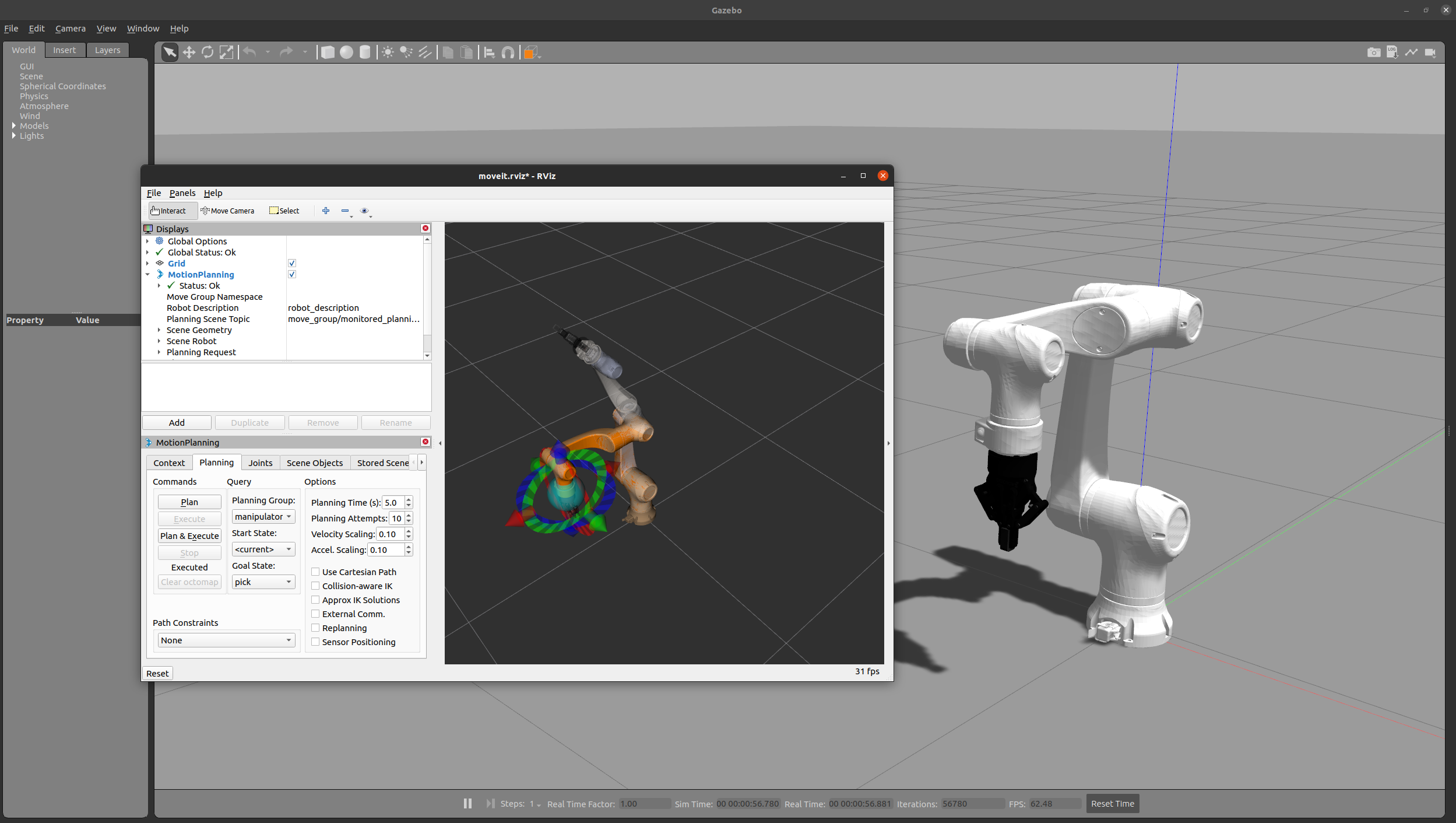
During testing, I ran into the issue that the robotic arm in RViz could plan and execute normally, but the robotic arm in Gazebo did not respond. For the fix, see this article.
II. Setting Up the Experiment Environment
The following section documents an earlier test setup using UR5 + Robotiq 2F-85.
2.1 Install the UR Robot and Drivers
After copying the code, modify the content below so it can run on ROS Noetic.
gedit ~/catkin_ws/src/universal_robot/ur_msgs/srv/SetPayload.srvfloat32 payload
geometry_msgs/Vector3 center_of_gravity
-----------------------
bool successgedit ~/catkin_ws/src/universal_robot/ur_msgs/CMakeLists.txtcmake_minimum_required(VERSION 2.8.3)
project(ur_msgs)
## Find catkin macros and libraries
## if COMPONENTS list like find_package(catkin REQUIRED COMPONENTS xyz)
## is used, also find other catkin packages
find_package(catkin REQUIRED COMPONENTS message_generation std_msgs geometry_msgs)
## Generate messages in the 'msg' folder
add_message_files(
FILES
Analog.msg
Digital.msg
IOStates.msg
RobotStateRTMsg.msg
MasterboardDataMsg.msg
RobotModeDataMsg.msg
ToolDataMsg.msg
)
## Generate services in the 'srv' folder
add_service_files(
FILES
SetPayload.srv
SetSpeedSliderFraction.srv
SetIO.srv
)
## Generate added messages and services with any dependencies listed here
generate_messages(
DEPENDENCIES
std_msgs
geometry_msgs
)
###################################
## catkin specific configuration ##
###################################
catkin_package(
# INCLUDE_DIRS include
# LIBRARIES ur_msgs
CATKIN_DEPENDS message_runtime std_msgs geometry_msgs
# DEPENDS system_lib
)
###########
## Build ##
###########
#############
## Install ##
#############
#############
## Testing ##
#############gedit ~/catkin_ws/src/universal_robot/ur_msgs/package.xml<?xml version="1.0"?>
<package format="2">
<name>ur_msgs</name>
<version>1.2.5</version>
<description>The ur_msgs package</description>
<author>Andrew Glusiec</author>
<author>Felix Messmer</author>
<maintainer email="g.a.vanderhoorn@tudelft.nl">G.A. vd. Hoorn</maintainer>
<maintainer email="miguel.prada@tecnalia.com">Miguel Prada Sarasola</maintainer>
<maintainer email="nhg@ipa.fhg.de">Nadia Hammoudeh Garcia</maintainer>
<license>BSD</license>
<buildtool_depend>catkin</buildtool_depend>
<build_depend>message_generation</build_depend>
<depend>std_msgs</depend>
<depend>geometry_msgs</depend>
<exec_depend>message_runtime</exec_depend>
<export>
</export>
</package>After that, you can build the workspace. After source, run roslaunch ur5_moveit_config demo.launch.
2.2 Simple Tests
(1) Open the UR5 model in RViz
The robotic arm and gripper model path is universal_robot/urdf/ur5_gripper_joint_limited_robot.urdf.xacro.
You can launch it with universal_robot/ur_description/launch/view_ur5_with_gripper.launch, view the model in RViz, and drag the robotic arm model with joint_state_publisher_gui.
# 无夹爪
roslaunch ur_description view_ur5.launch
# 有夹爪
roslaunch ur_description view_ur5_with_gripper.launch
(2) MoveIt test in RViz
Use the commands below to test MoveIt trajectory planning in RViz.
# 无夹爪
roslaunch ur5_moveit_config demo.launch
# 有夹爪
roslaunch ur5_gripper_moveit_config demo.launch
(3) MoveIt test in Gazebo
# 无夹爪
roslaunch ur_gazebo ur5.launch
roslaunch ur5_moveit_config ur5_moveit_planning_execution.launch sim:=true
roslaunch ur5_moveit_config moveit_rviz.launch config:=trueur5.launch: used to start the Gazebo simulation environment. Specifically, it starts an empty world, defines the robot_description parameter server, spawns the robot in Gazebo, and starts and loads controllers.
ur5_moveit_planning_execution.launch: used to start MoveIt-related components. Specifically, it sets the sim parameter, remaps the follow_joint_trajectory topic according to sim, and starts MoveIt.
moveit_rviz.launch: used to start RViz-related components. Specifically, it loads configuration parameters and starts RViz.
# 有夹爪
roslaunch ur_gazebo ur5_with_gripper.launch
roslaunch ur5_single_arm_moveit_config ur5_moveit_planning_execution.launch
roslaunch ur5_gripper_moveit_config moveit_rviz.launch config:=true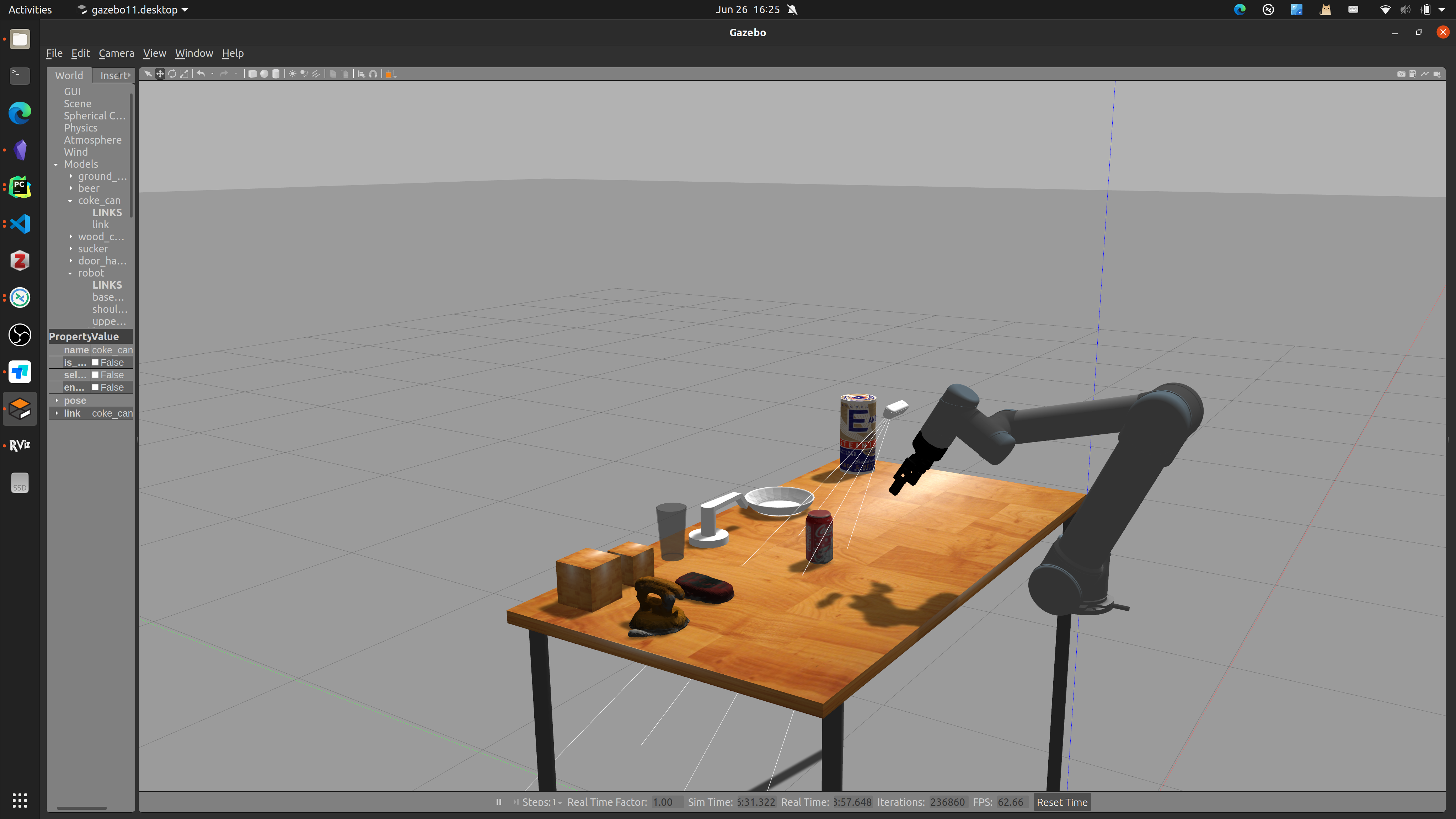
2.3 Import Custom Objects
(1) Online method
Load your object model in MeshLab.
Click Filters → Normals … → Compute normals for points sets and confirm with the default settings.
Click Filters → Remeshing → Surface Reconstruction: Screened Poisson and confirm with the default settings.
Click Filters → Texture → Parametrization: Trivial Per-Triangle and confirm with the settings below. Method is the important field.
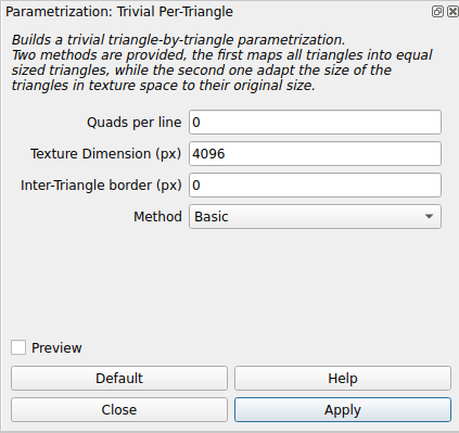
Click Filters → Texture → Transfer Vertex Attributes to Textur(1 or 2 meshes) and confirm with the settings below. Source Mesh and Target Mesh are the important fields.

(2) Trial-and-error method
Click Filters → Texture → Parametrization: Flat Plane.
Click Filters → Texture → Transfer Vertex Attributes to Textur(1 or 2 meshes).
Comments