Create the Gripper Geometry
If you have a gripper model created with other modeling software such as SolidWorks, you can import it into RobotStudio. Here, a simple model is created, mainly to demonstrate the process of creating a dynamic gripper.
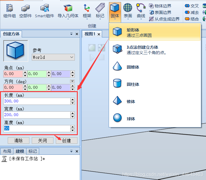
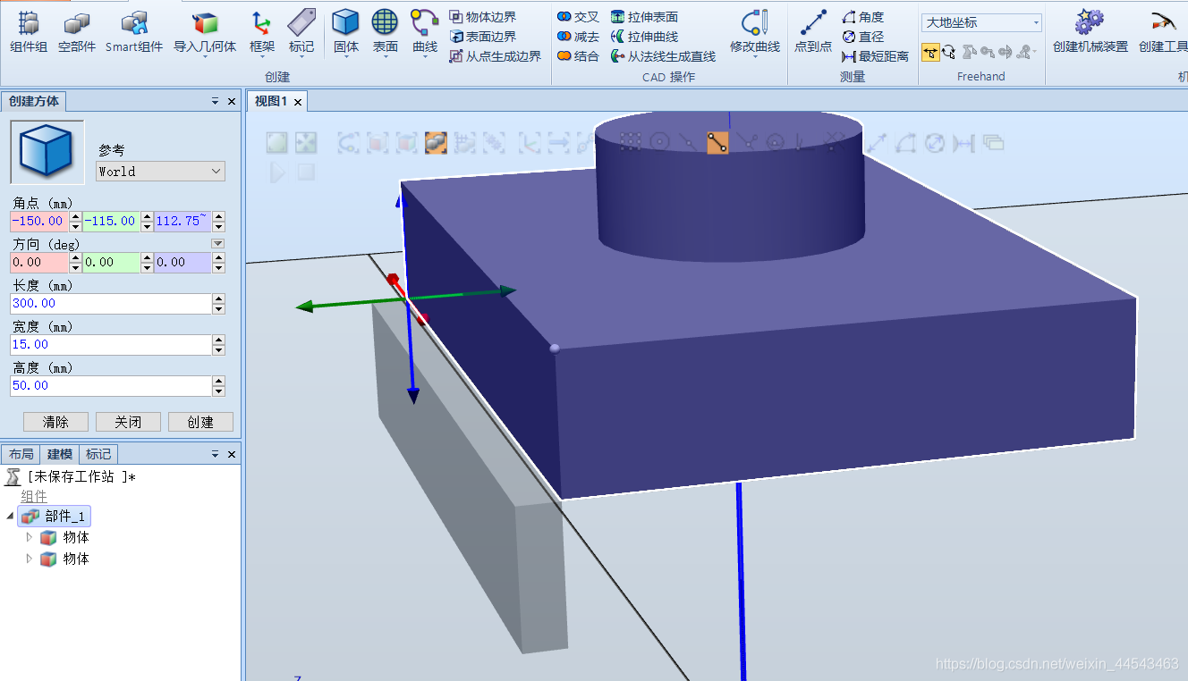
- Create the gripper body
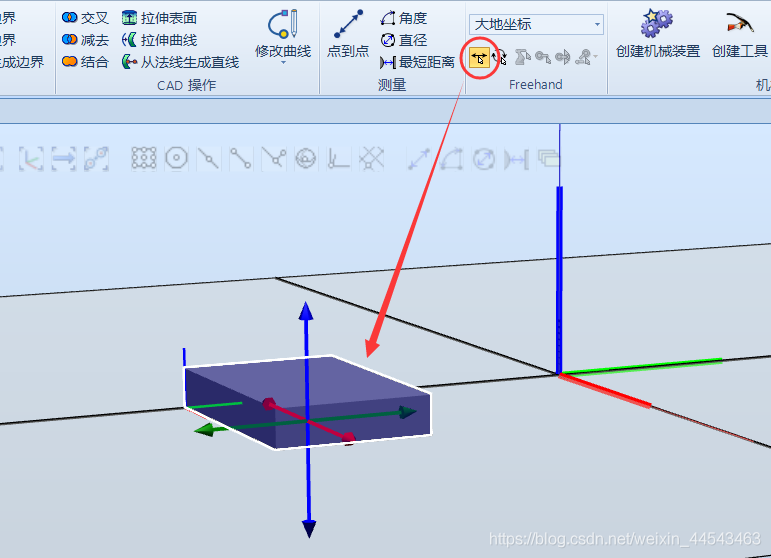
- Move it to another position in preparation for creating the other parts of the gripper
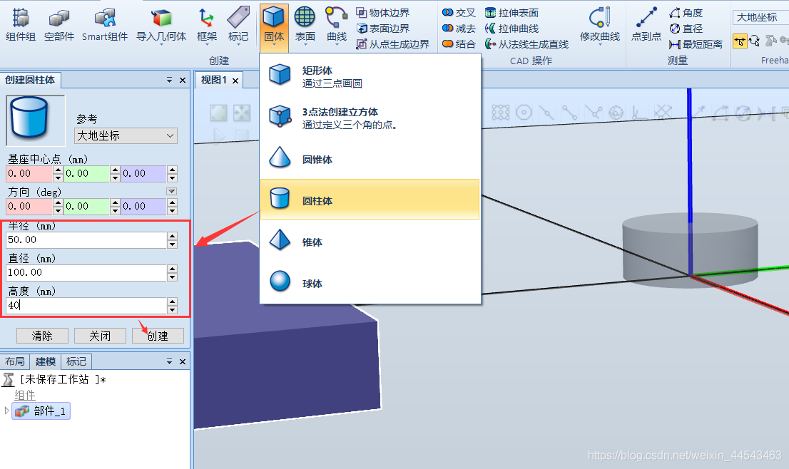
- Create a cylinder to serve as the gripper flange, which connects to the robot’s end joint
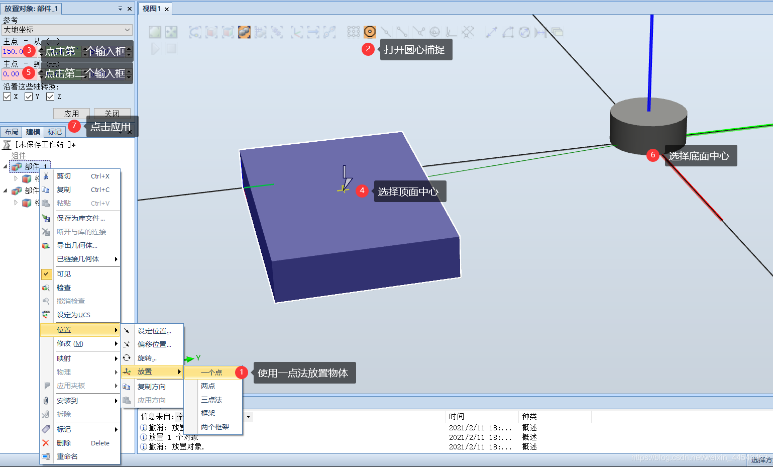
- Move the cuboid.
- Drag the object in Part 2 onto Part 1 to combine the two objects into one part.
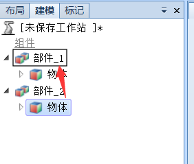
- Create the gripper fingers
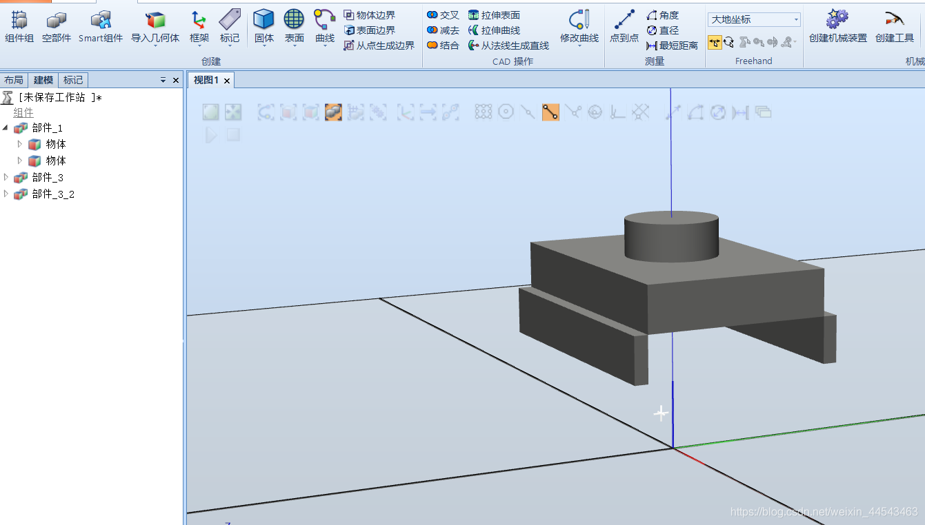
Create the Mechanism
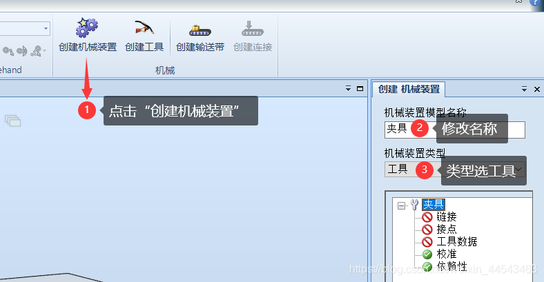
- Click Create Mechanism, enter “Gripper” as the mechanism name, and select “Tool” as the mechanism type
- Add links for each of the three parts created earlier. If you imported the model, you also need to add links for each part. Select BaseLink for the base part, but not for the other parts.
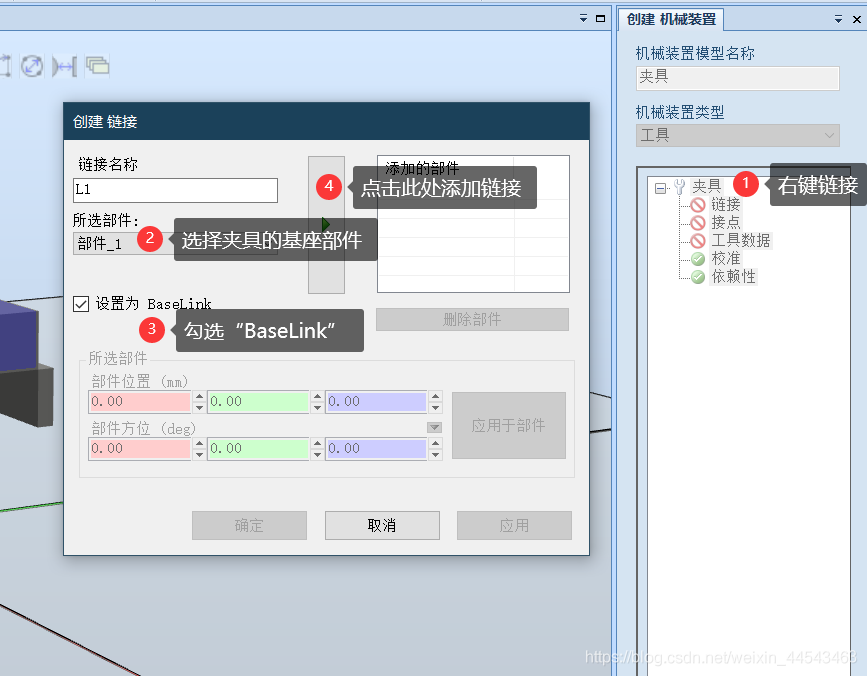
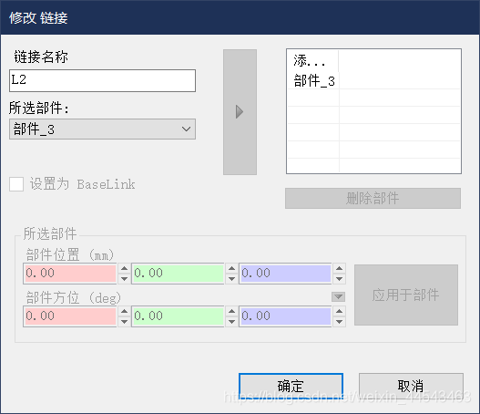
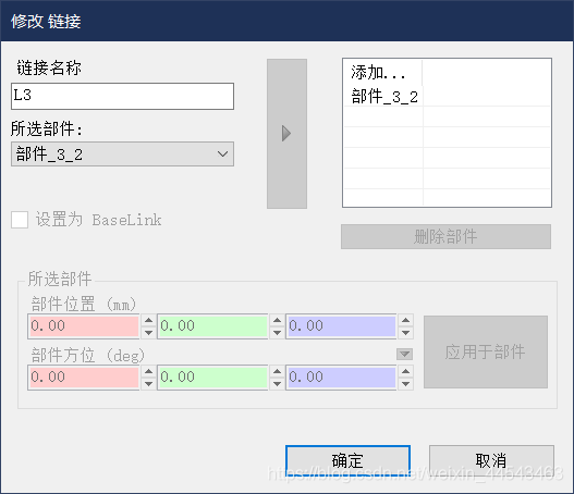

-
Create joints
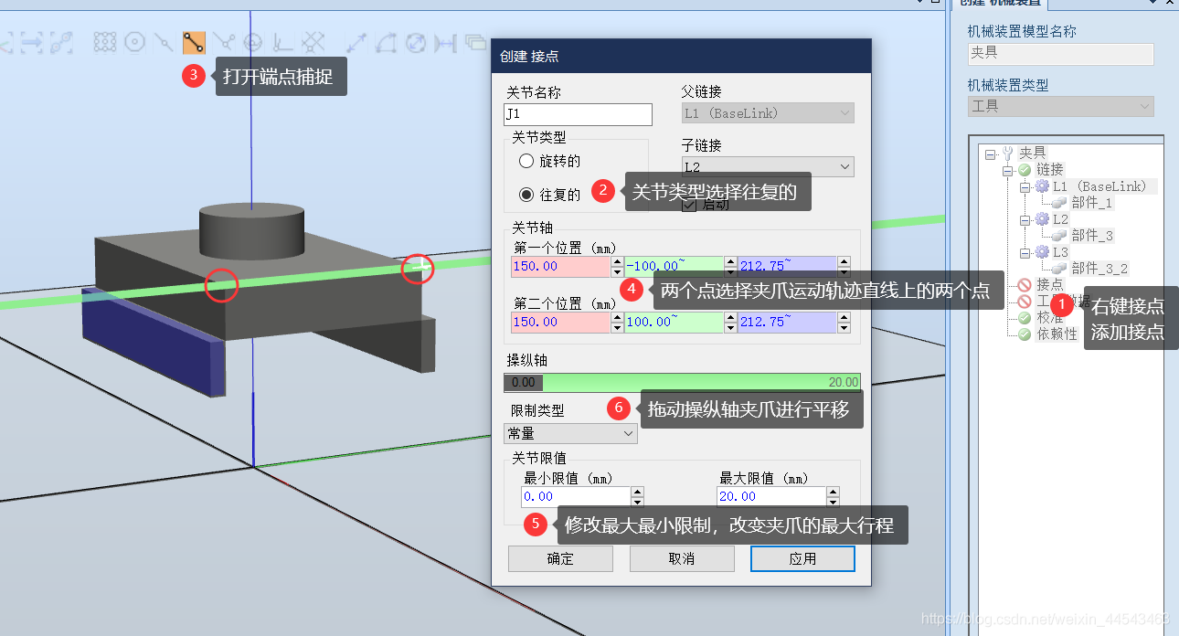
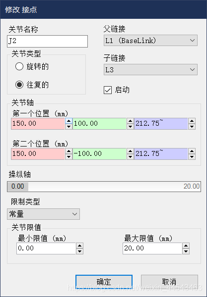
-
Create tool data
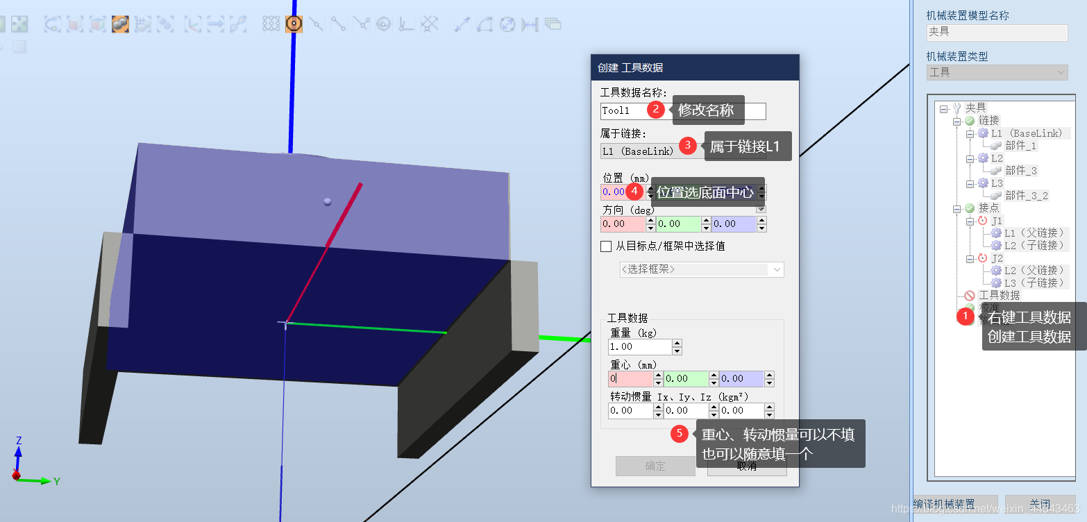
-
Add a new pose
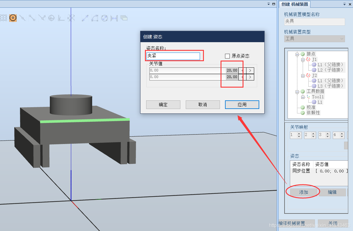
Configure the Smart Component
- Create a Smart Component, drag the gripper under the Smart Component, and set the gripper as the Smart Component’s Role
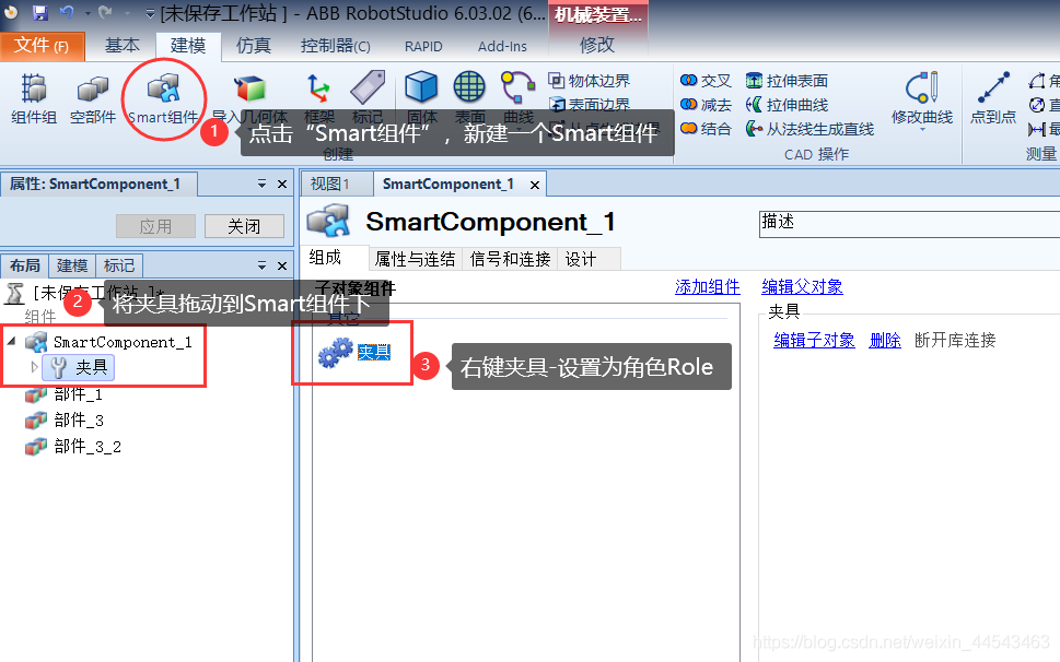
- Add the following components
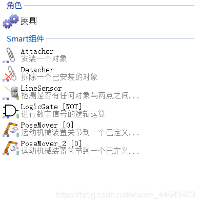
- Add signals

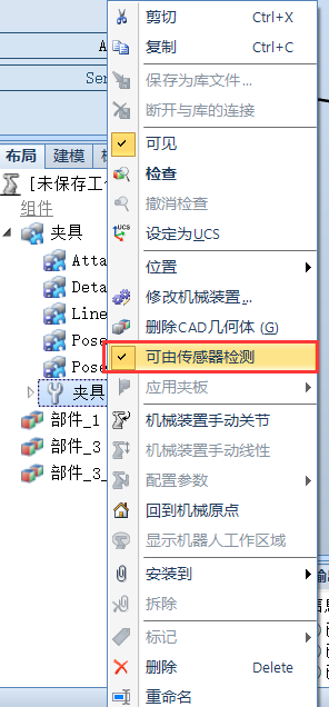
- Configure each component. First, set the gripper so that it cannot be detected by sensors
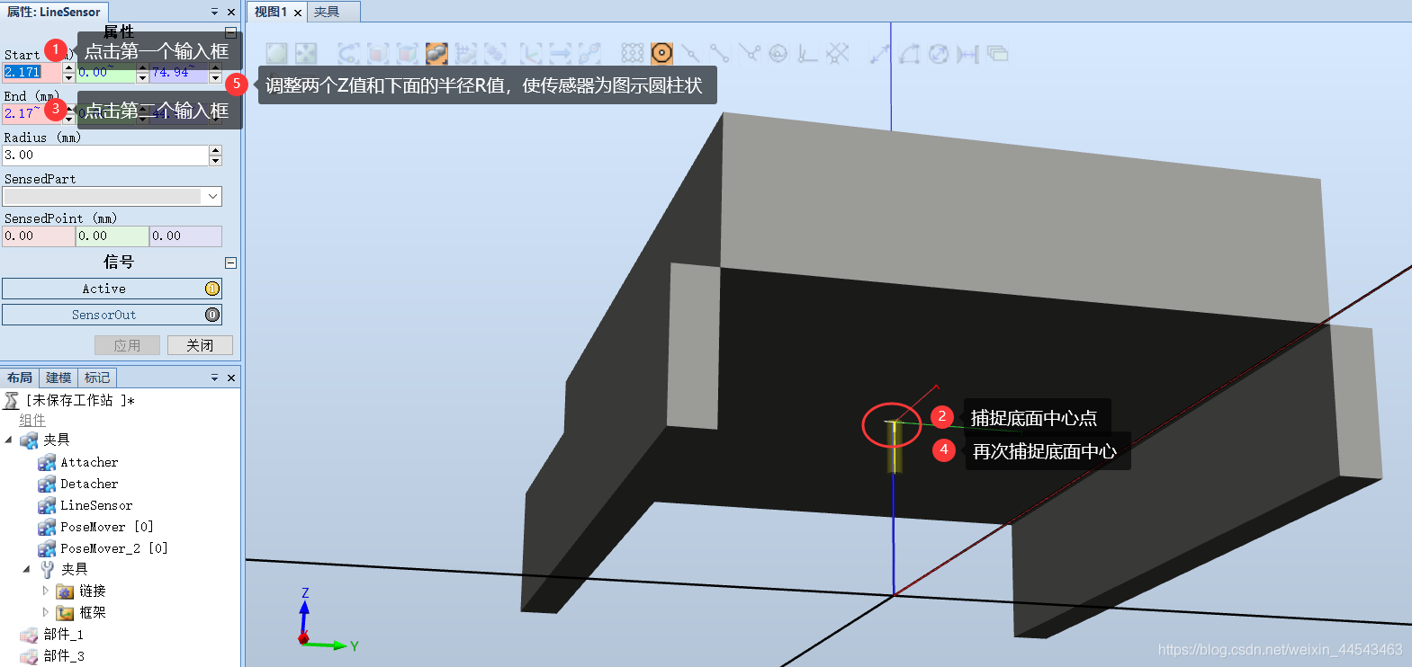
- Configure the Line Sensor in the cylindrical shape shown so that it detects whether an object is beneath the gripper
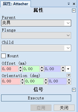
- Configure the Attacher component for attaching objects
- Configure PoseMover, which controls the mechanism’s movement properties
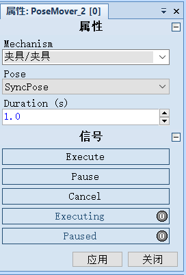
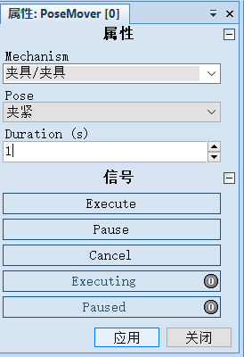
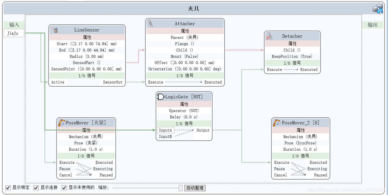
- Design the program block diagram as shown
Link: https://pan.baidu.com/s/1pVwEuCmvoiwFlHMjRqEjLQ Extraction code: rs04
Comments