I. L298N
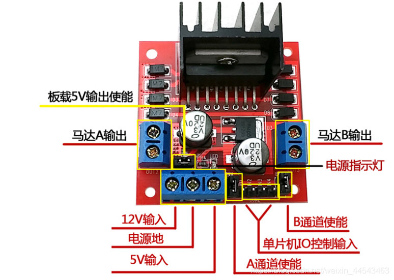 A microcontroller cannot drive a stepper motor directly, so an L298N is needed as the driver. The L298N has a maximum power consumption of 20W, a drive-terminal supply range of +5~+30V, a control-signal input voltage range of 5V/0V, and a peak drive current of 2A.
II. Two-Phase Four-Wire Stepper Motor
1. Specifications
(1)Number of phases: The number of coil groups inside the motor.
(2)Excitation step count: The number of pulses or energized states required to complete one periodic change in the magnetic field. A two-phase four-wire motor can be driven with a one-phase-on four-step sequence, a two-phase-on four-step sequence, or an eight-step sequence.
(3)Step angle: The angle through which the motor rotates for each change in the magnetic field. The step angle of a two-phase four-wire motor is 0.9°/1.8°.
2. Operating Principle
 As shown in the figure, the motor has four control signals: A+, A-, B+, and B-. The stepper motor’s rotation can be controlled by controlling the excitation pulses on these four wires. Taking the four-step drive mode as an example, the sequence for clockwise rotation is:
| STEP | A+ | A- | B+ | B- | |
|---|---|---|---|---|---|
| 1 | 1 | 0 | 0 | 0 | |
| 2 | 0 | 1 | 0 | 0 | |
| 3 | 0 | 0 | 1 | 0 | |
| 4 | 0 | 0 | 0 | 1 | |
| P.S.: The motor’s direction of rotation is determined by the pulse sequence, while its rotational speed is related to the pulse frequency. |
III. Wiring
- Control terminals: Connect IN1, IN2, IN3, and IN4 to four microcontroller pins to provide pulses.
- Input terminals: Connect the 5V input to the onboard 5V supply and the 12V input to an external power supply.
- Enable terminals: Connect ENA and ENB to the onboard 5V supply; they are enabled by default.
- Output terminals: Connect OUT1, OUT2, OUT3, and OUT4 to the stepper motor’s red, green, yellow, and blue wires, respectively.
III. Proteus Simulation
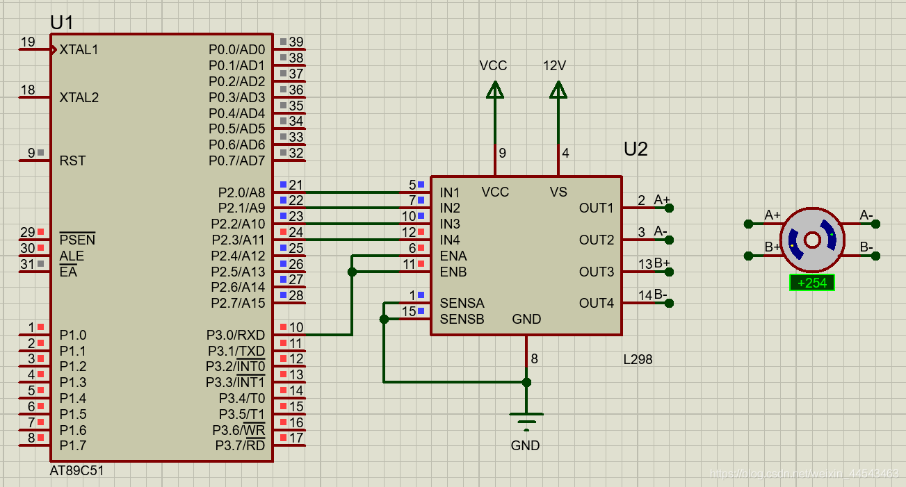
The wiring in Proteus is shown below:
 The comments in the reference program below identify the arrays for clockwise and counterclockwise rotation:
#include<reg52.h>
sbit enable = P3^0;

void delay(int i)
{
	int j;
	for(;i>0;i--)
		for(j=114;j>0;j--);
}

void main()
{
	unsigned char step[] = {0x01,0x02,0x04,0x08};	//顺时针转动
	//unsigned char istep[] = {0x01,0x02,0x04,0x08}; //逆时针转动
	int i=0;
	enable=1;
	while(1)
	{
		for(i=0; i<4; i++)
		{
			P2 = step[i];
			delay(200);
		}
	}
}
Simulation result:
Comments