Controlling a Stepper Motor with STM32
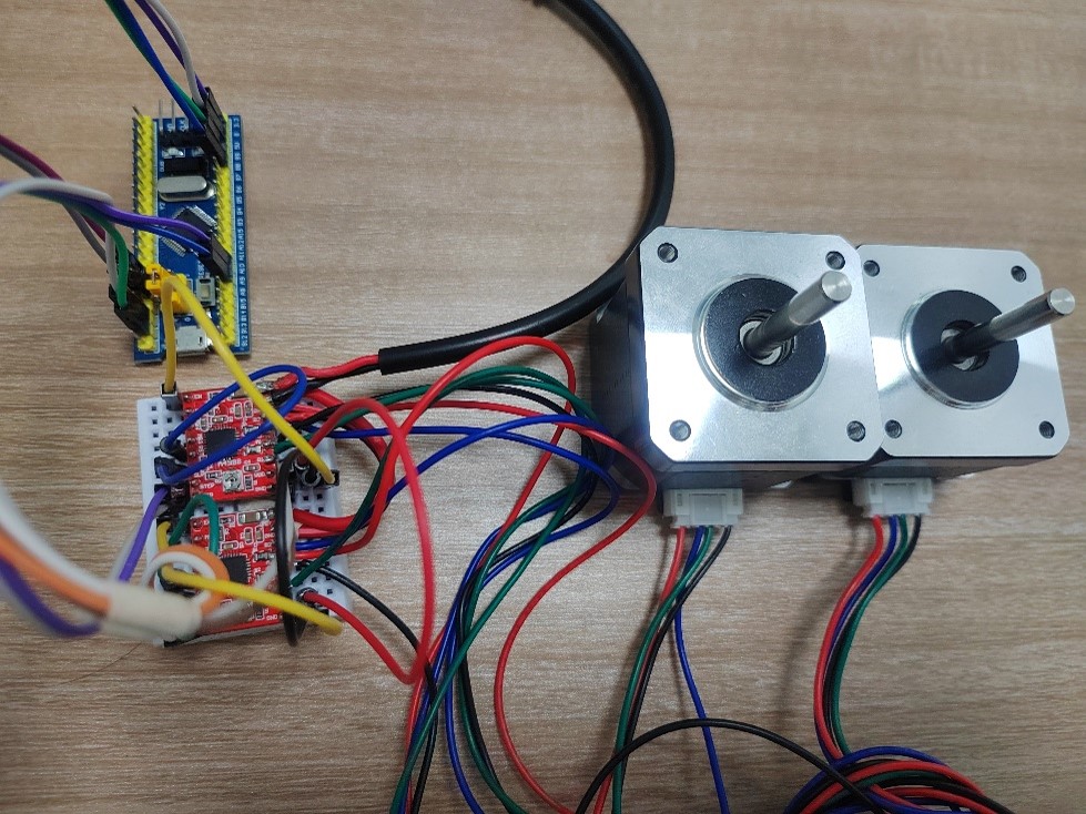
Driving a 42-series stepper motor with an A4988 chip, tested on the STM32F1 platform, with up to 16× microstepping.
36 posts
Driving a 42-series stepper motor with an A4988 chip, tested on the STM32F1 platform, with up to 16× microstepping.
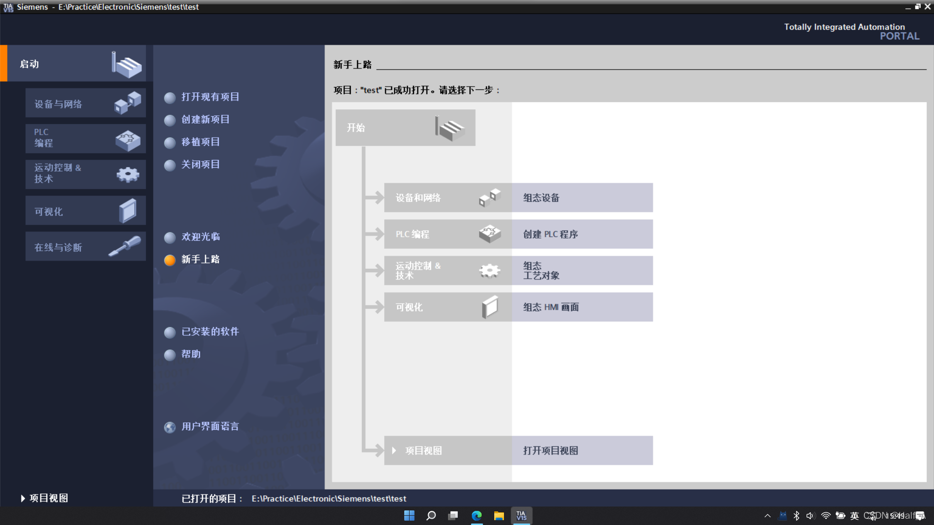
An installation guide for Siemens TIA Portal V15 PLC automation design software.
I was using an STM32F103C8T6 minimum system board. After debugging the STM32 program on Windows and successfully establishing serial communication, the serial connection stopped responding after I restarted the computer.
This tutorial explains how to download and install the Keil5 51 edition. Keil5 is a very user-friendly and powerful C language software development system. Keil5 provides a clear and intuitive interface, is very easy and convenient to use, and includes compiler, compiler, installer package, and debugging and tracing features.
This tutorial explains how to download and install the MDK edition of Keil5. Keil5 is a very user-friendly and powerful C software development system. Keil5 provides a clear, intuitive interface, is very easy and convenient to use, and includes a compiler, compiler, installation package, and debugging and tracing features.
LabVIEW 2020 Chinese edition installation tutorial with Aliyun Drive links and detailed installation steps. For learning reference only—do not use for commercial purposes!
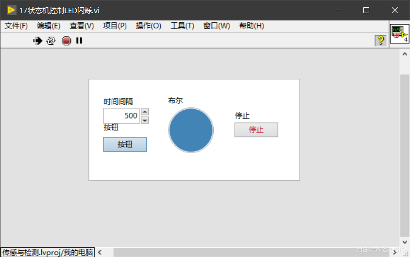
The state machine is the most commonly used design model in engineering applications. With a state machine, we can easily implement decisions and branches in a program flowchart. A LabVIEW state machine consists of a While Loop, a Case Structure, and a shift register.
State machines are the most widely used design pattern in engineering applications. With a state machine, we can easily implement decisions and branches from program flowcharts. A LabVIEW state machine consists of a While loop, a case structure, and a shift register.
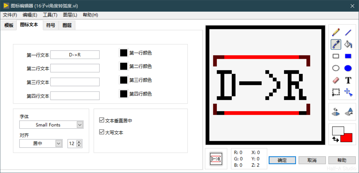
An important concept in programming is modularity, which means dividing a program into several blocks so that modifying one block does not affect the others. In LabVIEW, we use subVIs to implement modular programming.
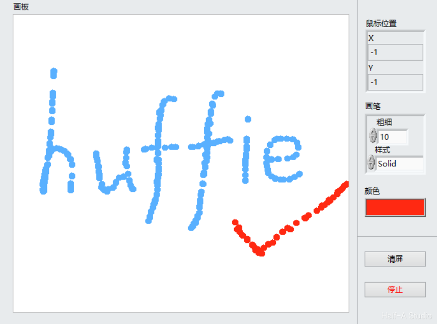
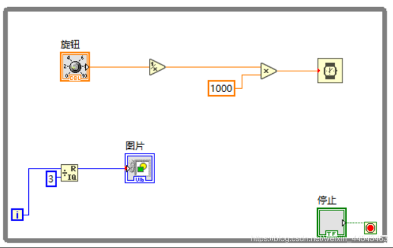
The two-dimensional Picture control provides pixel-level control and can create almost any graphical object. To display an image in a two-dimensional Picture control, you must write an image to the control programmatically. You can draw with the Picture Functions VIs.
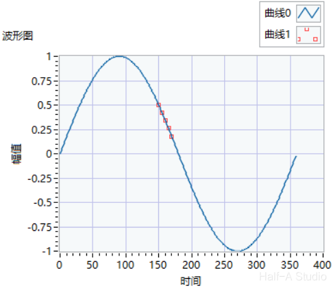
A shift register passes the value generated in the previous loop iteration to the next iteration. Shift registers appear as pairs of terminals located at corresponding positions on the borders on opposite sides of a loop. A shift register must be initialized; that is, you must set the value that it passes to the first loop iteration.
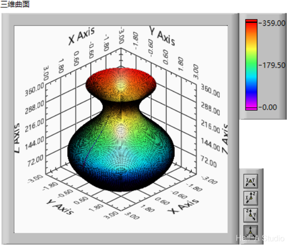
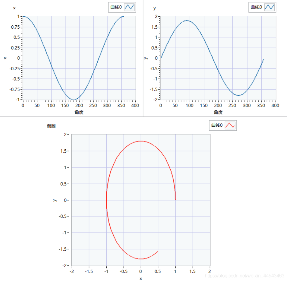
Generating a surface of revolution such as a vase essentially involves sweeping a profile along a guide curve. For a vase, the method is to sweep a circle along a curve. The circle is generated as follows: the total number of loop iterations is 360, corresponding to 360 degrees, while i represents each angle from 0~360.
A for loop runs for a fixed number of iterations and also has a conditional terminal that can terminate a while loop early, equivalent to the break statement in C. For loops are closely tied to array operations, and their most important function is processing array data.
The components used include a simulated power supply, a transformer, a bridge rectifier, a non-polarized capacitor, an electrolytic capacitor, and a three-terminal voltage regulator IC. The wiring method is shown in the figure.
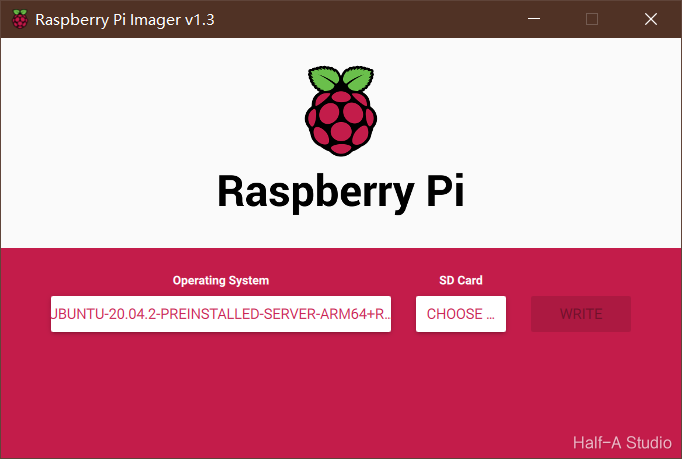
Go to the official Ubuntu website and download the Ubuntu installation package for Raspberry Pi. Use DiskGenius to format the SD card, delete all sectors, and then format it. Download the official imaging tool, select the .xz file you just downloaded as the image, select your SD card, and write the image. Then configure the Ubuntu environment...
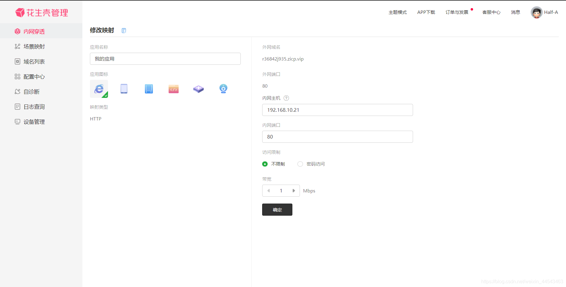
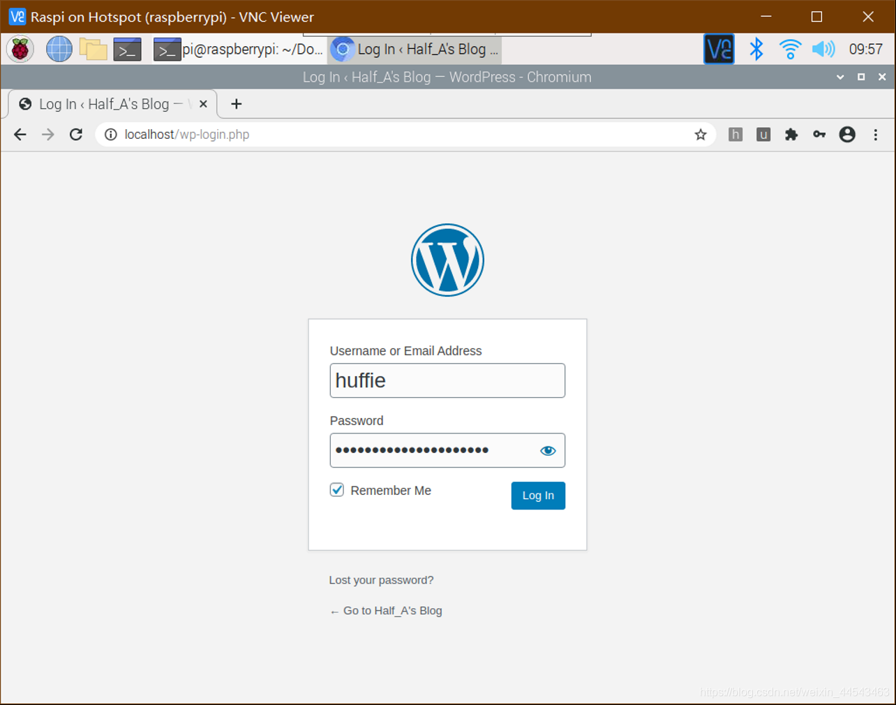
After WordPress has been installed and configured, you can access the website by entering localhost or the Raspberry Pi's IP address in a browser. However, it still cannot be accessed from the external network (outside the same router). The purpose of NAT traversal is to allow computers on the external network to access your website. To make the setup less difficult and complex, I used PeanutHull.
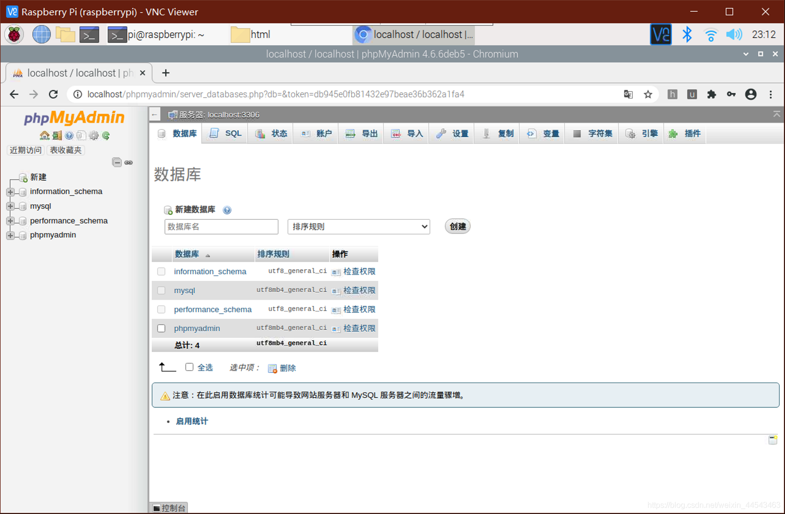
Download the installation package from the official WordPress website, extract it, and place the contents of the worpress folder in the html folder. Enter localhost/phpmyadmin in your browser to open phpMyAdmin, enter your phpMyAdmin username and password, click the Databases tab, create a new database, enter a database name, and click Create. No database tables are needed for now.
Setting up a personal website on a Raspberry Pi mainly involves the following steps—setting up a LAMP server (Linux + Apache + MySQL + PHP) and creating a database user (this step requires installing PhpMyAdmin and using SQL statements to add a MariaDB database user).
Raspberry Pi installation, configuration, and remote access mainly involve the following steps—preparing the TF card, downloading and writing the image, determining and accessing the IP address, updating and configuring package sources, and implementing Windows remote access. At this point, the initial system installation is complete and you can enter the graphical interface.
Case structures are similar to if…else… and switch structures in C and are mainly used to select among branches of program logic. A case structure contains two or more subdiagrams or cases. Only one case executes at a time. Right-click the case structure border to add, duplicate, delete, reorder, or select the default case. Multiple input/output tunnels can be created.
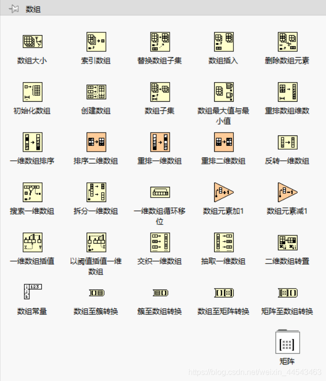
When processing a series of similar data and performing repeated calculations, consider using an Array. An Array groups data elements of the same type. Place an Array shell on the front panel and drag a data object or element into the shell to create an Array. Array functions such as Array Size, Index Array, Build Array, Array Max & Min, Sort, and Split Array can all be performed with Array functions.
Property nodes provide access to object properties. In applications that may need to programmatically change the appearance of front panel objects in response to specific inputs, these changes can be configured by editing property nodes. Right-click a control on the block diagram to create a property node. To configure multiple properties, drag the top or bottom border to add properties. A property node executes its properties from top to bottom.
The purpose of variables is to transfer data between parallel loops. Shift registers can transfer data generated by the previous iteration to the next iteration. Right-click the loop border to add a shift register. The shift register on the right stores the data at the end of each iteration, while the shift register on the left provides the stored data to the next iteration.
A While Loop executes at least once, while a For Loop can execute 0 times. A While Loop automatically outputs the value from the last iteration, while a For Loop automatically outputs an array. You can right-click the border of a While Loop and convert it to a For Loop from the shortcut menu.
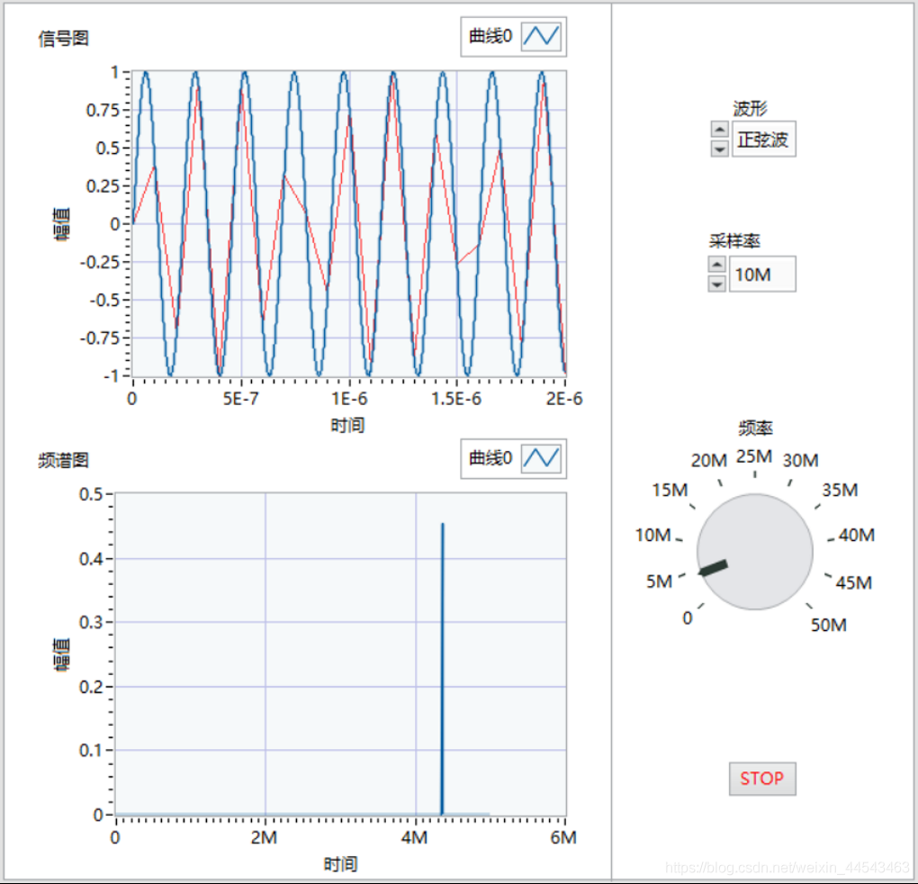
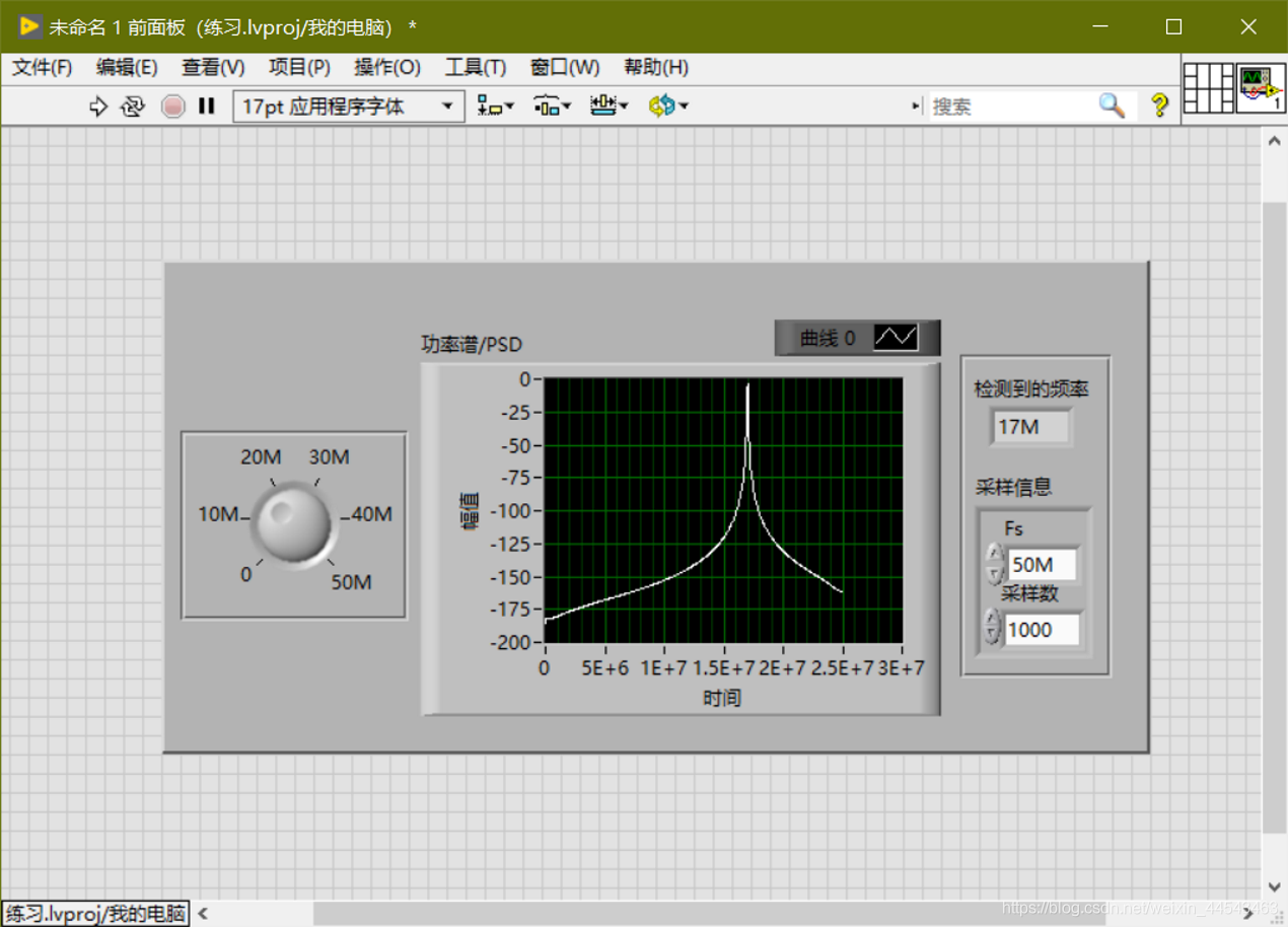
Generate a sine-wave signal with a frequency of 0-50M; choose a sampling rate of 10M/50M/100M; detect the signal frequency; output the sampled signal's power spectrum; and restart averaging if the frequency or sampling rate changes.
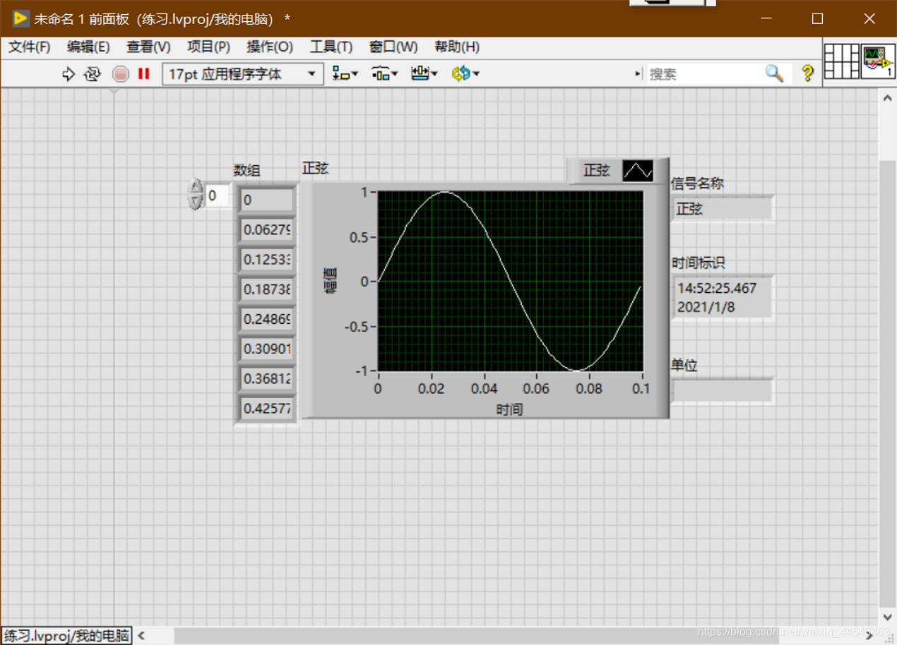
In LabVIEW, the dynamic data type is shown in dark blue. Only Express VI can produce and receive ExpressVI. Use the Get Dynamic Data ExpressVI to retrieve the properties of dynamic data, and use the Set Dynamic Data Attributes ExpressVI to set properties such as the signal name, timestamp, and time mode.
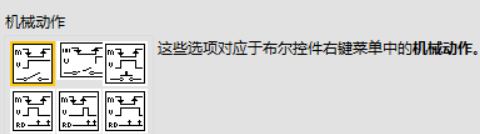
Numeric controls can represent different types of numeric values. The most important setting for Boolean controls is the mechanical action. The display type of string controls can be changed from the shortcut menu. To add items to a control's drop-down list and reorder them, right-click an enum or ring control and select Edit Items from the shortcut menu, or click the Edit Items tab in the Properties dialog box.
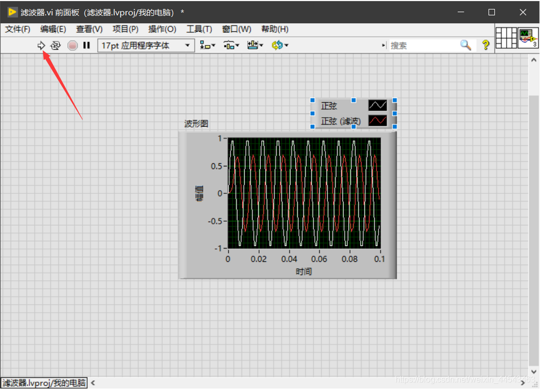
Place an Express VI on the block diagram, configure the dialog box that appears, wire the Express VI, then save and run the VI.
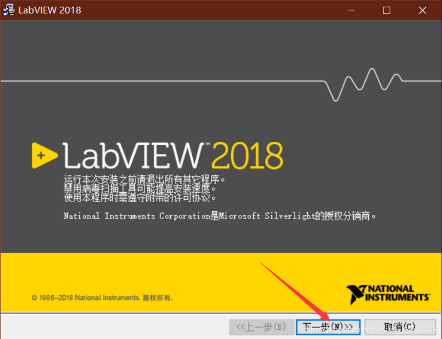
If you need a different version, see the resources page. Download the LabView2018.zip archive from Baidu Netdisk. Before installation, create a new folder for the LabVIEW installation path. It is best not to install it in the root directory of a drive.
Controls come from the Controls palette. Right-click to open the Controls palette. You can add a control to the front panel by clicking it or dragging it. A block diagram consists of terminals (from the front panel), subVIs, functions, constants, structures, and wires.
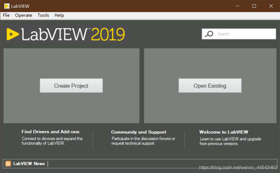
This release is the English version. For the Chinese version, see the resources page. Download the LabView2019.zip archive from the cloud drive, extract it and open the corresponding 64-bit or 32-bit folder, then extract the ISO file inside that folder, open the extracted folder, and double-click install.exe to install.
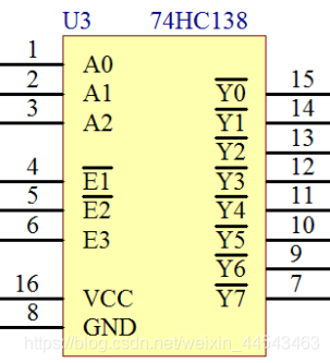
When designing MCU circuits, the number of MCU I/O pins is limited and sometimes cannot meet our design requirements. To control more devices, we need peripheral digital chips for pin expansion. A common choice is the 74HC138, also called a three-to-eight (38) decoder.
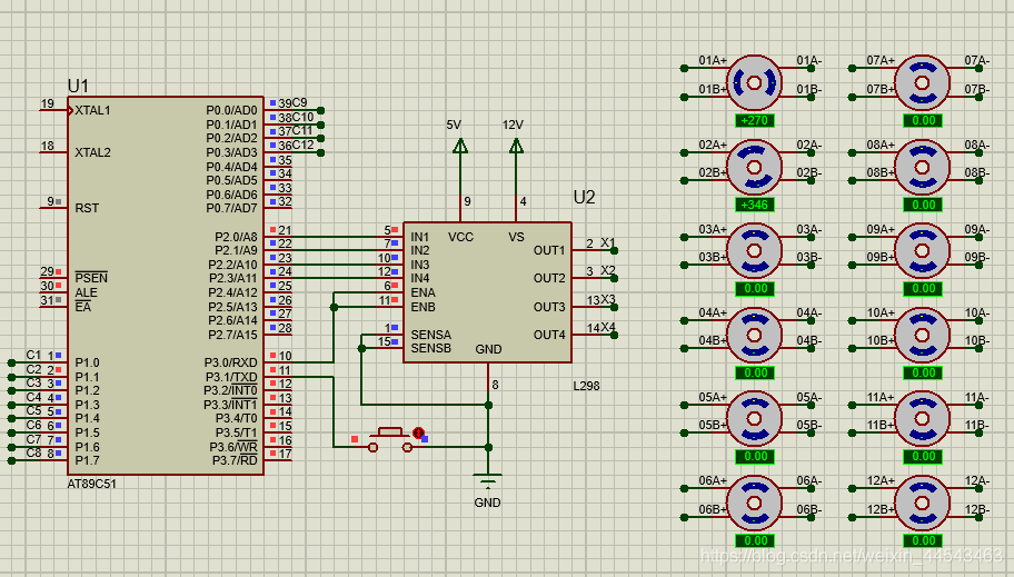
The CD4066 is a quad bilateral analog switch. Connect the four inputs of the CD4066 to the L298N outputs and the CD4066 outputs to the stepper motor's A+, A-, B+, and B- terminals. Tie all four control pins to one MCU pin so a single pin can switch all four switches on the CD4066 together, enabling stepper motor selection.
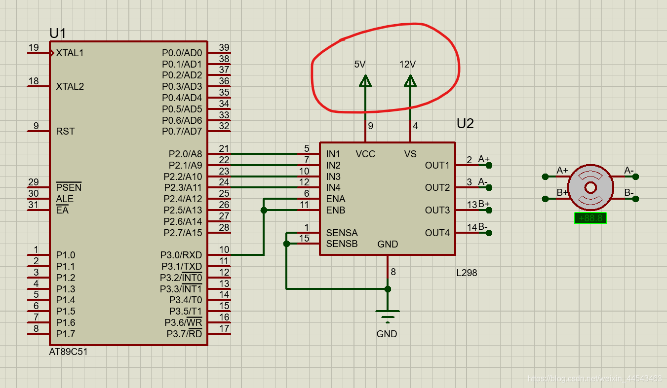
Solution: Choose Design—Configure Power Rails. Under Power Supplies, add the power supply that is not connected to a net to the list of connected nets.
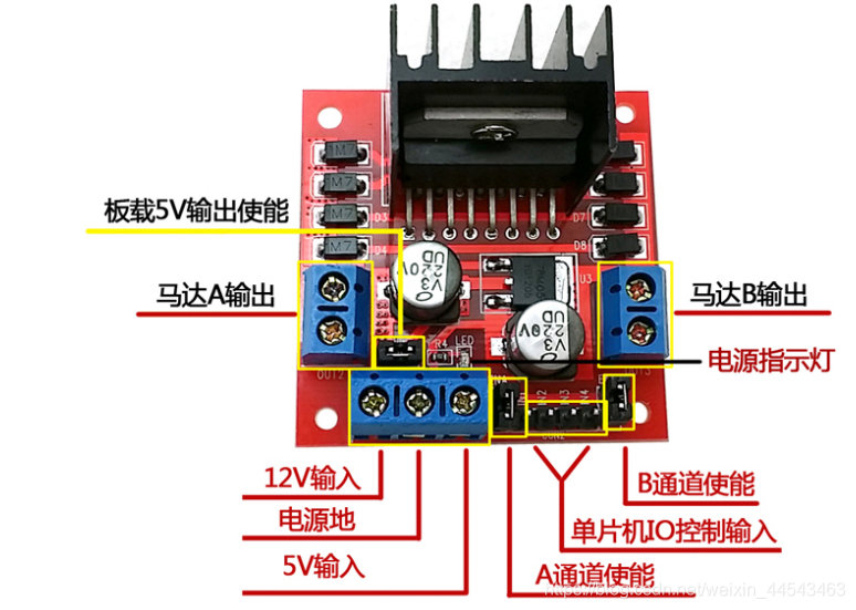
A microcontroller cannot drive a stepper motor directly, so an L298N is needed as the driver. This article introduces some L298N parameters, along with the drive principles and methods for a two-phase four-wire stepper motor. A simulation experiment is also performed in Proteus based on the drive principles described.
This experiment uses an ESP8266 NodeMCU. The firmware flashed is the official NodeMCU firmware. Open the official ESP8266Flasher, select the NodeMCU firmware in the Config tab, and set the flash address to 0x00000.