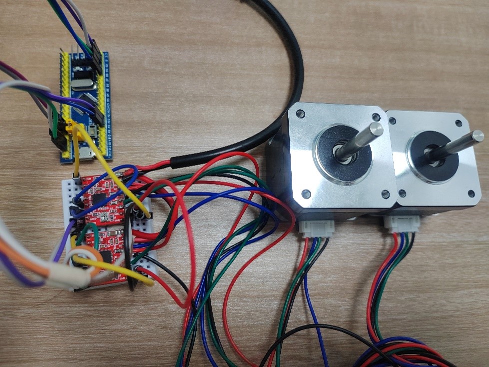
Hardware used: an STM32F103C8T6 minimum system board, an A4988 module, and a 42-series stepper motor (42BYGH39).
1.1 Introduction to the A4988
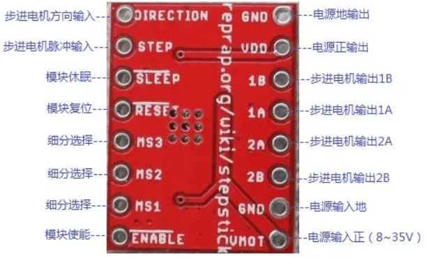
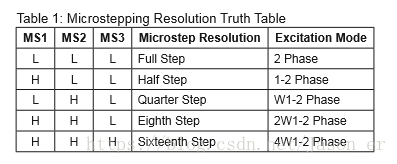
| Pin | Function | Wiring |
|---|---|---|
| EN | Enable input, active low | Connect to GND or MCU IOx1 |
| MS1/2/3 | Step mode selection | Leave unconnected or use MCU IOx3 |
| SLP | Sleep, active high | Short to RST |
| STEP | Pulse input; one pulse produces one step | MCU IOx1 |
| DIR | Direction bit; 0/1 each represents a direction | MCU IOx1 |
| VMOT/GND | Power interface, 8~35V DC, maximum 2A | 12/24V power supply |
| 1A/1B/2A/2B | Stepper motor wiring | Stepper motor |
| VDD/GND | Connect to the MCU’s 3.3V and GND | MCU power supply |
1.2 Wiring
STM32 and USB-to-TTL
| STM32 | USB-to-TTL |
|---|---|
| 3.3V/5V | 3.3/5V |
| GND | GND |
| PA9 | RXD |
| PA10 | TXD |
STM32 and A4988
| STM32 | A4988 |
|---|---|
| 3.3V/5V | VDD |
| GND | GND |
| PB6 | STEP (defined in motor.h) |
| PB7 | DIR (defined in motor.h) |
| Connect EN to GND | |
| Connect SLP to RST |
A4988 and the stepper motor
| A4988 | Stepper motor |
|---|---|
| VMOT | 12V power supply + |
| GND | 12V power supply - |
| B2 | B- |
| A2 | B+ |
| A1 | A+ |
| B1 | A- |
Pay attention to the phase sequence when wiring the stepper motor
On the A4988, the labels are 1A, 1B, 2A, and 2B. The numbers indicate the phase, while a and b indicate positive and negative.
On the stepper motor, the labels are A+, A-, B+, and B-. A and B indicate the phase, while + and - indicate positive and negative.
The corresponding wiring should therefore be: A+ and A- correspond to 1A and 1B, while B+ and B- correspond to 2A and 2B. For example, on my stepper motor, black is A+, green is A-, red is B+, and blue is B-. For the corresponding A4988 terminals B2 A2 A1 B1, the motor wire order is B- B+ A+ A- (blue-red-black-green).
Incorrect wiring may cause the motor to rotate in reverse or only vibrate without rotating.
1.2 Program Design
This program controls the stepper motor over the serial port. It is adapted from the development board’s serial-port example, with additional stepper motor driver functions.
The delay between GPIO transitions represents the speed. delay_ms(2) gives approximately 0.8s per revolution, while delay_ms(1) gives approximately 0.4s per revolution.
By default (full-step mode), one STEP pulse rotates the stepper motor by 90°.
//motor.h
#ifndef __MOTOR_H
#define __MOTOR_H
#include "delay.h"

//PF0-7,12-15

#define Motor_GPIO GPIOF				//PF
#define Motor_RCC RCC_APB2Periph_GPIOF
//第一个步进电机A4988的接线
#define Motor1_STEP	GPIO_Pin_1	//STEP - PF1
#define Motor1_DIR	GPIO_Pin_2	//DIR  - PF2
//第二个步进电机A4988的接线	//PB
#define Motor2_STEP	GPIO_Pin_3	//STEP - PF3
#define Motor2_DIR	GPIO_Pin_4	//DIR  - PF4

void MOTOR_Init(void);
void motor(unsigned int motor1_dir, unsigned int motor1_step, unsigned int motor2_dir, unsigned int motor2_step);


#endif
//motor.c
#include "motor.h"
/*GPIO_motornum和GPIOx用于选择电机,GPIO_direction用于选择电机方向,dir:0为逆1为正,k为90°的倍数*/
// GPIO
void MOTOR_Init()
{
GPIO_InitTypeDef GPIO_InitStructure;
RCC_APB2PeriphClockCmd(Motor_RCC,ENABLE);
//Motor初始化
GPIO_InitStructure.GPIO_Pin = Motor1_STEP|Motor1_DIR|Motor2_STEP|Motor2_DIR;
GPIO_InitStructure.GPIO_Mode=GPIO_Mode_Out_PP;
GPIO_InitStructure.GPIO_Speed = GPIO_Speed_50MHz;
GPIO_Init(Motor_GPIO,&GPIO_InitStructure); // 初始化GPIOB
GPIO_ResetBits(Motor_GPIO,Motor1_STEP); //初始化GPIOB_6输出低电平
GPIO_ResetBits(Motor_GPIO,Motor1_DIR); //初始化GPIOB_7输出低电平
GPIO_ResetBits(Motor_GPIO,Motor2_STEP); //初始化GPIOB_8输出低电平
GPIO_ResetBits(Motor_GPIO,Motor2_DIR); //初始化GPIOB_9输出低电平
}
void motor(unsigned int motor1_dir, unsigned int motor1_step, unsigned int motor2_dir, unsigned int motor2_step)
{
unsigned int i;
switch(motor1_dir)
{
case 0 : GPIO_SetBits(Motor_GPIO,Motor1_DIR); break;
case 1 : GPIO_ResetBits(Motor_GPIO,Motor1_DIR); break;
default : break;
}
switch(motor2_dir)
{
case 0 : GPIO_SetBits(Motor_GPIO,Motor2_DIR); break;
case 1 : GPIO_ResetBits(Motor_GPIO,Motor2_DIR); break;
default : break;
}
/*
GPIO_SetBits(Motor_GPIO,Motor1_STEP);
GPIO_SetBits(Motor_GPIO,Motor2_STEP);
delay_ms(2); //周期1.3ms
GPIO_ResetBits(Motor_GPIO,Motor1_STEP);
GPIO_ResetBits(Motor_GPIO,Motor2_STEP);
delay_ms(2);
*/
for(i = 0;i < motor1_step || i < motor2_step; i++)
{
if(i<motor1_step)
{
GPIO_SetBits(Motor_GPIO,Motor1_STEP);
delay_ms(2); //周期1.3ms
GPIO_ResetBits(Motor_GPIO,Motor1_STEP);
delay_ms(2);
}
if(i<motor2_step)
{
GPIO_SetBits(Motor_GPIO,Motor2_STEP);
delay_ms(2); //周期1.3ms
GPIO_ResetBits(Motor_GPIO,Motor2_STEP);
delay_ms(2);
}
}
//delay_ms(2); //延时一会
}
//main.c
#include "delay.h"
#include "sys.h"
#include "usart.h"
#include "mbotLinuxUsart.h"//引用该头文件是使用,通信协议的前提
#include "motor.h"

#define IMAGE_WIDTH		640/2
#define IMAGE_HEIGHT	480/2

//测试发送变量
short testSend1   =1111;
short testSend2   =2222;
short testSend3   =3333;
unsigned char testSend4 = 0x05;

//测试接收变量
int testRece1     =400;
int testRece2     =300;
unsigned char testRece3 = 0x00;


int main(void)
{
//=======================================变量定义=====================================================
	u8 dir1;
	u8 dir2;
	u16 step1;
	u16 step2;
//======================================硬件初始化====================================================
	delay_init();	    	                        //延时函数初始化
	NVIC_PriorityGroupConfig(NVIC_PriorityGroup_2); //设置中断优先级分组2
	uart_init(115200);	                            //串口初始化为115200
	MOTOR_Init();				 //初始化A4988驱动

//=======================================循环程序=====================================================
	while(1)
	{
		//将需要发送到ROS的数据,从该函数发出,前三个数据范围(-32768 - +32767),第四个数据的范围(0 - 255)
		usartSendData(testSend1,testSend2,testSend3,testSend4);
		if(testRece1>IMAGE_WIDTH)
		{
			dir1=1;
			step1=testRece1-IMAGE_WIDTH;
		}
		else
		{
			dir1=0;
			step1=IMAGE_WIDTH-testRece1;
		}
		if(testRece2>IMAGE_HEIGHT)
		{
			dir2=0;
			step2=testRece2-IMAGE_HEIGHT;
		}
		else
		{
			dir2=1;
			step2=IMAGE_HEIGHT-testRece2;
		}
		motor(dir1,step1,dir2,step2);
		//必须的延时
		delay_ms(13);
	}
}

//====================================串口中断服务程序=================================================
void USART1_IRQHandler()
{
	if(USART_GetITStatus(USART1, USART_IT_RXNE) != RESET)
 	 {
		 USART_ClearITPendingBit(USART1,USART_IT_RXNE);//首先清除中断标志位
		 //从ROS接收到的数据,存放到下面三个变量中
		 usartReceiveOneData(&testRece1,&testRece2,&testRece3);
	 }
}
//===========================================END=======================================================
1.3 Experiment
The STM32 obtains the coordinates of the target center in the image from the ROS system. receiveData1 stores the target’s x value, while receiveData2 stores the target’s y value.
Because the ROS system continuously sends coordinate values, the STM32 receives data in real time for control. The A4988 uses 16× microstepping. Each drive operation (50 loops) steps 5.625°, or 0.1° per loop. Consider setting the step size for each command according to the target offset. For example, for each difference of 1 coordinate unit, add one 0.1° loop to each command.
Comments