Contents
- I. Robot Modeling Tools
- II. URDF Models
- 2.1 Introduction to URDF Models
- 2.2 Creating a Package
- 2.3 Creating a URDF Model
- III. Xacro Models
- 3.1 Xacro Usage Example
- 3.2 Mathematical Expressions
- 3.3 Converting xacro to URDF
- IV. Example: A 7-DOF Robotic Arm
- 4.1 Introduction to the 7-DOF Robotic Arm
- 4.2 Preparations Before Creation
- 4.3 Detailed Explanation of the Model Code
- 4.4 Simulation in RViz
Why create a three-dimensional robot model? Robot simulation tools can help us identify critical errors in a design. Model simulation means that we create a robot model, so it does not necessarily look exactly like the real robot. However, because it is a simulation, the model must include all the characteristics of the real hardware.
I. Robot Modeling Tools
ROS provides many packages that help us model robots and use ROS for simulation, including urdf, kdl_parser, robot_state_publisher, collada_urdf, and others.
URDF is a robot model description format based on the XML specification. It connects components in a tree structure, so robot components can only be rigidly connected through joints.
1. robot_mode robot_model is a package collection containing many packages, including urdf. It can help us create three-dimensional robot models.
2. URDF-Related Packages
- joint_state_publisher: Reads the robot model description file, publishes information about each joint, and can use RViz for simulation to verify the rotational and translational relationships between joints.
- kdl_parser: Publishes joint states and performs forward and inverse kinematics analysis.
- robot_state_publisher: Reads the current robot joint states and publishes the robot’s pose.
3. xacro xacro is an upgraded version of urdf that makes urdf easier to read. xacro can also be used to describe complex robot models.
II. URDF Models
2.1 Introduction to URDF Models
1. Introduction to URDF
URDF is a robot model description format. You create a .urdf file and use XML tags to describe the robot model.
2. Common URDF Tags
- robot: Describes the entire robot model and defines the robot’s name, links, and joints.
<robot name="name of robot">
	<link>......</link>
	<link>......</link>

	<joint>......</joint>
	<joint>......</joint>
</robot>- link: Describes the appearance properties of a robot rigid body with
<visual />, including its size, shape, and color. It can also describe dynamic properties such as inertial parameters with<inertial>and collision properties with<collision>.
<link name="name of link">
	<visual>............</visual>
	<inertial>..........</inertial>
	<collision>.........</collision>
</link>- joint: Represents a robot joint. It can define the robot’s kinematic and dynamic parameters and can also constrain the robot’s motion and speed. Different joint tags represent the following joint types:
| joint tag | Joint type represented |
|---|---|
<revolute> | Revolute joint (with angular limits) |
<continuous> | Revolute joint (unlimited rotation) |
<prismatic> | Prismatic joint |
<fixed> | Fixed joint |
<float> | Floating joint |
<planar> | Planar joint |
<joint name="name of joint">
	<parent link="link1">
	<child link="link2">
	<calibration>......</calibration>
	<dynamics damping ....../>
	<limit effort ....../>
</joint>- gazebo: Contains simulation parameters for the Gazebo simulator. This tag can be used to include Gazebo plugins, configure Gazebo physics properties, and more.
<gazebo reference="link1">
	<material>Gazebo/Black</material>
</gazebo>
2.2 Creating a Package
1. First, enter the catkin workspace
cd ~/catkin_ws/srcIf you have not created a ROS workspace before, you can first run the following commands to create one:
mkdir -p ~/catkin_ws/src
cd ~/catkin_ws/src
catkin_init_workspace
catkin_make
source devel/setup.bash
echo "source /opt/ros/noetic/setup.bash" >> ~/.bashrc
2. Create the package
catkin_create_pkg robot_description_pkg roscpp tf geometry_msgs urdf rviz xacro3. Create the basic directories
cd robot_description_pkg
mkdir urdf meshes launch
The urdf directory is mainly used to store robot model description files; meshes stores model files; and the launch directory stores launch files. We need to create a launch file to start RViz and display the robot model.
2.3 Creating a URDF Model
Consider a pan-and-tilt mechanism, as shown below.
1. Create a urdf file
Enter the urdf directory created above, create a pan_tilt.urdf file, and enter the following code.
<?xml version="1.0"?>
<robot name="pan_tilt">

		<!--定义了base_link -->
		<!-- <visual>标签描述了在仿真环境的外观,包括几何外形<geometry>(圆柱形cylinder)等-->
        <link name="base_link">
                <visual>
                        <geometry>
                                <cylinder length="0.01" radius="0.2" />
                        </geometry>
                        <origin rpy="0 0 0" xyz="0 0 0" />
                        <material name="yellow">
                                <color rgba="1 1 0 1" />
                        </material>
                </visual>
        </link>

		<!-- 定义了关节pan_joint,以及其关节类型:旋转副(有限制) -->
		<!-- 旋转副连接的两个刚体分别为base_link和pan_link -->
        <joint name="pan_joint" type="revolute">
                <parent link="base_link" />
                <child link="pan_link" />
                <origin xyz="0 0 0.1" />
                <axis xyz="0 0 1" />
                <limit effort="300" velocity="0.1" lower="-3.14" upper="3.14" />
                <dynamics damping="50" friction="1" />
        </joint>

        <link name="pan_link">
                <visual>
                        <geometry>
                                <cylinder length="0.4" radius="0.04" />
                        </geometry>
                        <origin rpy="0 0 0" xyz="0 0 0.09" />
                        <material name="red">
                                <color rgba="0 0 1 1" />
                        </material>
                </visual>
        </link>

        <joint name="tilt_joint" type="continuous">
                <parent link="pan_link" />
                <child link="tilt_link" />
                <origin xyz="0 0 0.2" />
                <axis xyz="0 1 0" />
                <limit effort="300" velocity="0.1" lower="-4.64" upper="-1.5"/>
    			<dynamics damping="50" friction="1"/>
        </joint>

        <link name="tilt_link">
                <visual>
                        <geometry>
                                <cylinder length="0.4" radius="0.04" />
                        </geometry>
                        <origin rpy="0 1.5 0" xyz="0 0 0" />
                        <material name="green">
                                <color rgba="1 0 0 1" />
                        </material>
                </visual>
        </link>

</robot>
2. Check the urdf file
check_urdf pan_tilt.urdfIf the urdf file has no problems, it will output the following information:

3. Create a launch file
Enter the launch directory created earlier, create a view_demo.launch file, and add the following content:
<launch>
    <arg name="model" />
    <param name="robot_description" textfile="$(find robot_description_pkg)/urdf/pan_tilt.urdf" />
    <param name="use_gui" value="true" />

    <node name="joint_state_publisher_gui" pkg="joint_state_publisher_gui" type="joint_state_publisher_gui" />
    <node name="robot_state_publisher" pkg="robot_state_publisher" type="robot_state_publisher" />
    <node name="rviz" pkg="rviz" type="rviz" args="-d $(find robot_description_pkg)/urdf.rviz" required="true" />
</launch>
4. Start the nodes and view the simulated model First, build the workspace:
cd ~/catkin_ws
catkin_make
Then start the nodes:
roslaunch robot_description_pkg view_demo.launch After it opens, you will see an Unknown frame map message. Simply change Fixed Frame to base_link.
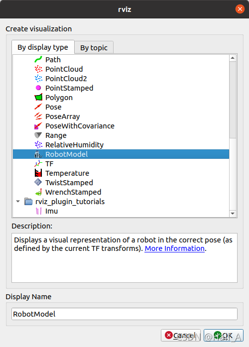
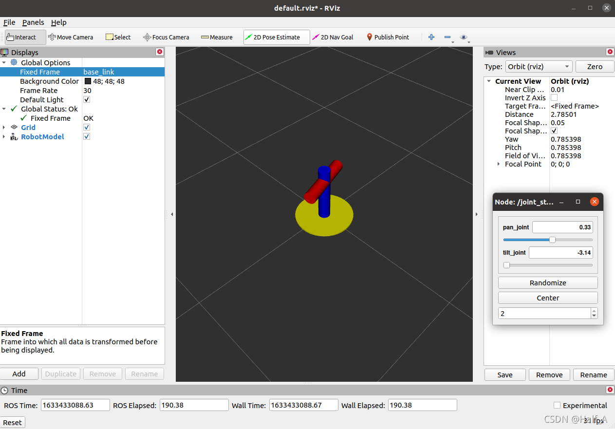
Then click Add in the lower-left corner and add RobotModel to display the robot model correctly.
III. Xacro Models
Although URDF models are simple, they have some problems. For example, code reuse is poor because repeated code can only be copied, and modularity is poor because other URDF files cannot be referenced. Xacro is an enhanced version of URDF. It describes models by creating macros. These macros can be reused and referenced by other files, making the code more readable.
3.1 Xacro Usage Example
Define frequently changed parameter values together at the beginning of the file. This makes them easier to change because you do not have to find and replace each parameter individually in the code.
<xacro:property name="base_link_length" value="0.01" />
<xacro:property name="base_link_radius" value="0.2" />

<xacro:property name="pan_link_length" value="0.4" />
<xacro:property name="pan_link_radius" value="0.04" />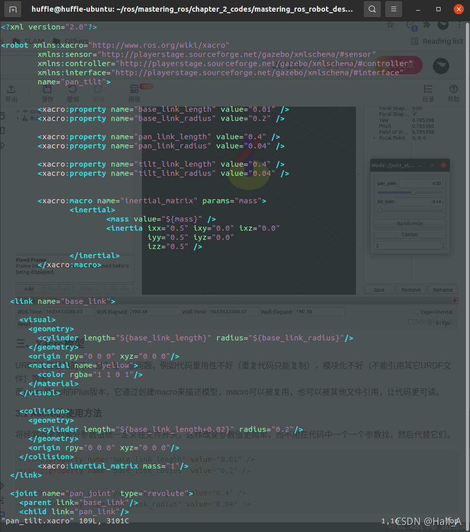
3.2 Mathematical Expressions
Basic mathematical operations can be performed in ${} within xacro tags. Supported operations include +, -, ×, and ÷. Exponentiation and modulo operations are not supported.
3.3 Converting xacro to URDF
After writing a xacro model file, you can use the following command to convert it to urdf. The xacro and urdf files before and after conversion appear on the two sides of >, respectively.
rosrun xacro xacro.py filename.xacro > newfilename.urdfIV. Example: A 7-DOF Robotic Arm
4.1 Introduction to the 7-DOF Robotic Arm
We know that determining a robotic arm’s end-effector pose requires 6 degrees of freedom (3 coordinates +3 directions). A seven-DOF robotic arm is therefore a kinematically redundant manipulator: we can obtain different joint configurations for the same pose. This effectively improves the robot’s flexibility and functionality and makes it easier to avoid collisions.
4.2 Preparations Before Creation
① Robotic Arm Specifications
| Item | Parameter |
|---|---|
| Degrees of freedom | 7 |
| Robotic arm length | 50cm |
| Reach | 35cm |
| Number of rigid bodies | 12 |
| Number of joints | 11 |
② Joint List
| No. | Joint name | Joint type | Angular limit |
|---|---|---|---|
| 1 | bottom_joint | Fixed | — |
| 2 | shoulder_pan_joint | Revolute | -150~114 |
| 3 | shoulder_pitch_joint | Revolute | -67~109 |
| 4 | elbow_roll_joint | Revolute | -150~41 |
| 5 | elbow_pitch_joint | Revolute | -92~110 |
| 6 | wrist_roll_joint | Revolute | -150~150 |
| 7 | wrist_pitch_joint | Revolute | 92-113 |
| 8 | gripper_roll_joint | Revolute | -150~150 |
| 9 | finger_joint1 | Prismatic | 0~3cm |
| 10 | finger_joint2 | Prismatic | 0~3cm |
4.3 Detailed Explanation of the Model Code
The code mainly consists of the following parts: ① Constant Definitions Define commonly used mathematical constants and parameter values for each rigid body of the robotic arm. For example, the following code snippet defines a mathematical constant and the shoulder rigid body’s parameter values, respectively.
  <!-- Constants -->
  <property name="M_SCALE" value="0.001 0.001 0.001"/>
  <property name="M_PI" value="3.14159"/>

  <!-- Shoulder pan link properties -->
  <property name="shoulder_pan_width" value="0.04" />
  <property name="shoulder_pan_len" value="0.08" />
② Inertia Matrix Definition
   <xacro:macro name="inertial_matrix" params="mass">
      <inertial>
      	<mass value="${mass}" />
        <inertia ixx="1.0" ixy="0.0" ixz="0.0" iyy="0.5" iyz="0.0" izz="1.0" />
      </inertial>
   </xacro:macro>
③ Transmission Configuration
The <transmission> tag defines the joint connected to an actuator. It can define the motor type and parameters, the type of hardware interface, the ROS controller interface, and more.
   <xacro:macro name="transmission_block" params="joint_name">
	  <transmission name="tran1">
	    <type>transmission_interface/SimpleTransmission</type>
	    <joint name="${joint_name}">
	      <hardwareInterface>PositionJointInterface</hardwareInterface>
	    </joint>
	    <actuator name="motor1">
	      <hardwareInterface>PositionJointInterface</hardwareInterface>
	      <mechanicalReduction>1</mechanicalReduction>
	    </actuator>
	  </transmission>
   </xacro:macro>
④ Referencing Other xacro Files
You can reference other xacro files by using the <xacro:include> tag.
<xacro:include filename="$(find mastering_ros_robot_description_pkg)/urdf/sensors/xtion_pro_live.urdf.xacro"/>⑤ Inserting Simple Models As with urdf, use the mesh tag to insert basic shapes such as cylinders and rectangular prisms.
  <link name="bottom_link">

    <visual>
      <origin xyz=" 0 0 -0.04"  rpy="0 0 0"/>
      <geometry>

	       <box size="1 1 0.02" />

      </geometry>
      <material name="Brown" />
    </visual>

    <collision>
      <origin xyz=" 0 0 -0.04"  rpy="0 0 0"/>
      <geometry>
	       <box size="1 1 0.02" />
      </geometry>
      </collision>>

  </link>
4.4 Simulation in RViz
① Convert the xacro file into a urdf model
First, enter the directory containing the xacro file, then run the following code to convert the .xacro file into a .urdf file:
rosrun xacro xacro seven_dof_arm.xacro > seven_dof_arm.xacro.urdfThen check whether the urdf file was generated correctly:
check_urdf seven_dof_arm.xacro.urdf② Edit the launch file Enter the launch directory and edit the launch file as follows. It is basically the same as in the previous section, so it is not explained in detail again.
<launch>
    <arg name="model" />
    <param name="robot_description" textfile="$(find robot_description_pkg)/urdf/seven_dof_arm.xacro.urdf" />
    <param name="use_gui" value="true" />

    <node name="joint_state_publisher_gui" pkg="joint_state_publisher_gui" type="joint_state_publisher_gui" />
    <node name="robot_state_publisher" pkg="robot_state_publisher" type="robot_state_publisher" />
    <node name="rviz" pkg="rviz" type="rviz" args="-d $(find robot_description_pkg)/urdf.rviz" required="true" />
</launch>
③ Build and Run
cd ~/catkin_ws
catkin_make
roslaunch robot_description_pkg view_arm.launch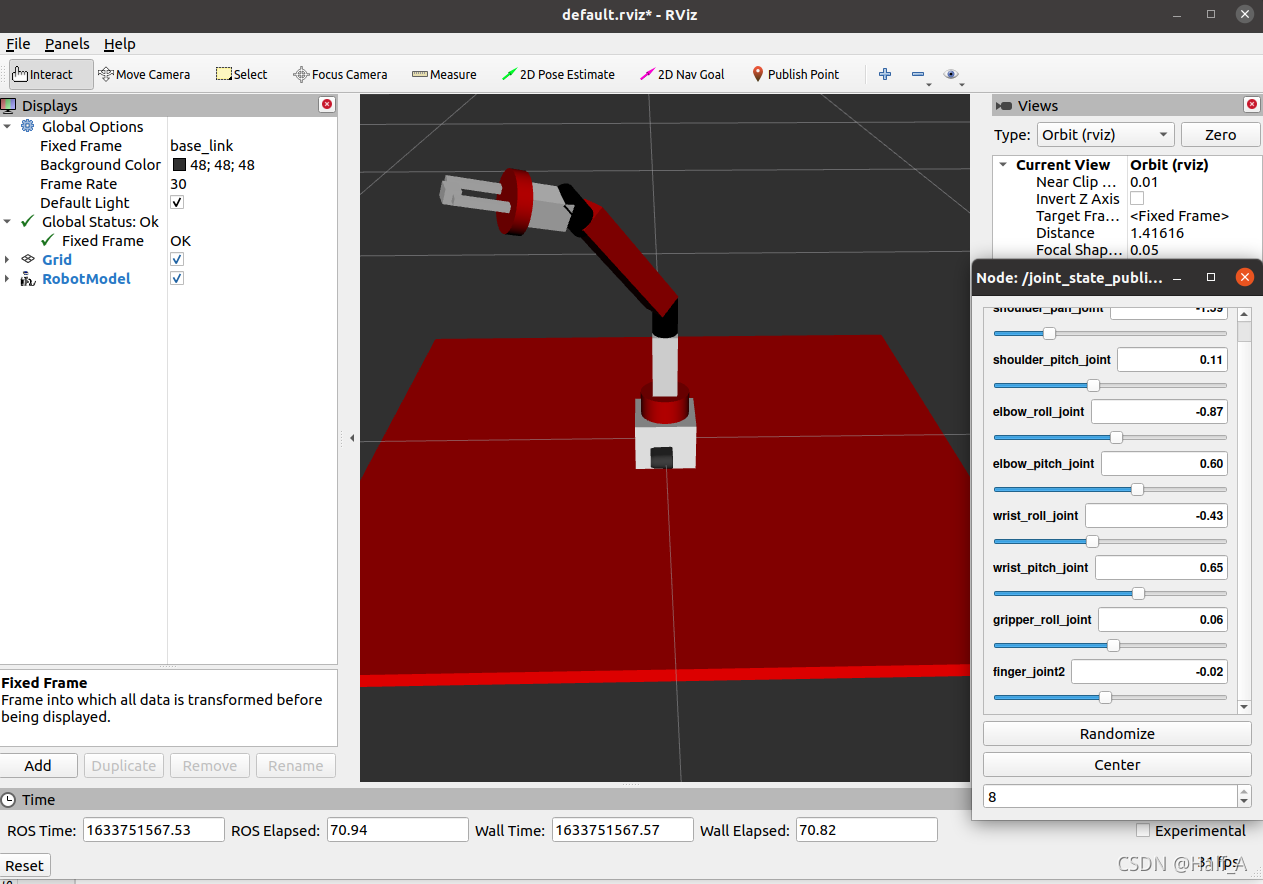
Package files Link: https://huffie.lanzouw.com/ieTZMv5t3fi
Comments