Contents
I. Introduction to State Machines
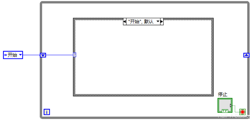
State machines are the most widely used design pattern in engineering applications. With a state machine, we can easily implement decisions and branches from program flowcharts. A LabVIEW state machine consists of a While loop, a case structure, and a shift register. The While loop keeps the program running continuously. The code in each branch of the case structure describes each state of the state machine and the selection of the next state. The shift register passes the choice made in the previous state to the selector terminal in the next iteration.
II. Basic Framework of a State Machine
On the block diagram, create a While loop, add a shift register to the While loop, then create a case structure inside the While loop. The case structure’s selector terminal is an enum constant.
III. Example
3.1 Runtime Behavior
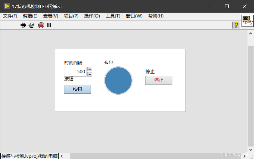
After you press the start button, the LED blinks at the configured time interval. Press the stop button to stop the program.
3.2 Block Diagram
The block diagram is shown below:
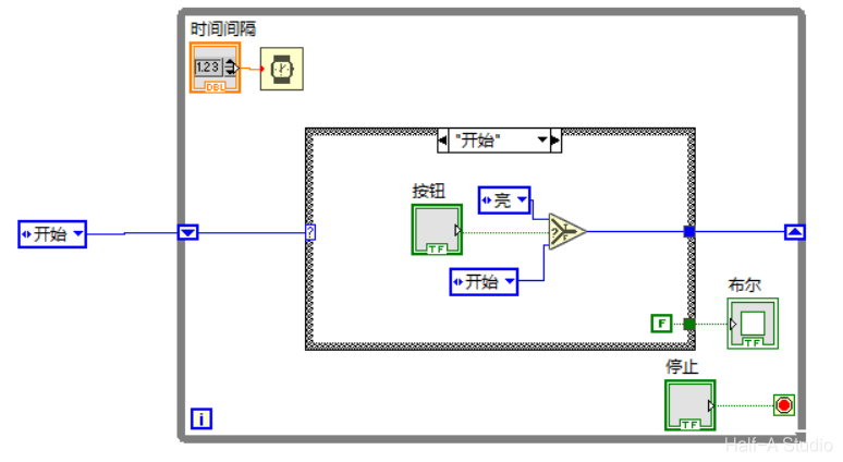
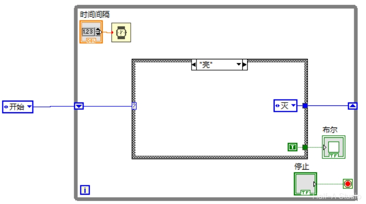
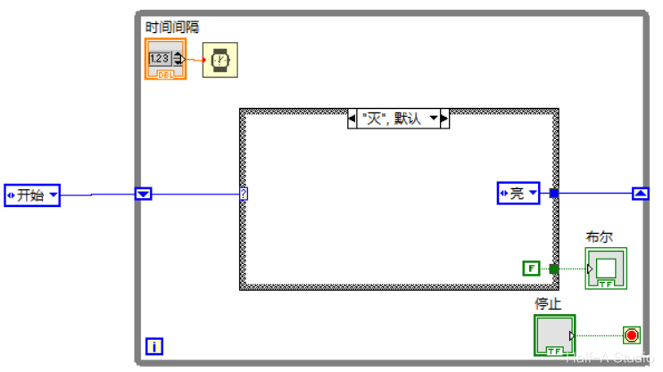
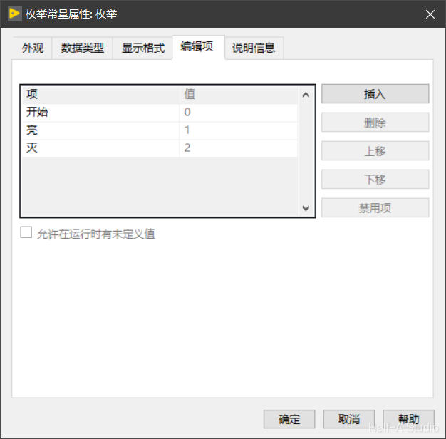
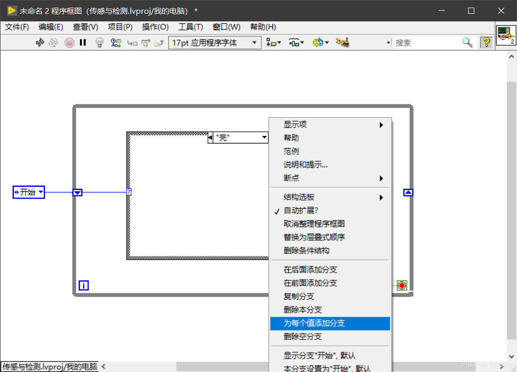
Enum branch configuration is as follows: Set three items to “Start”, “On”, and Off. Then at the case structure branches, right-click - Add Case for Every Value The initial value on the left and the value inside the “Start” branch are both the same enum constant (created by copy and paste).
3.3 Program Logic
-
The initial input to the case selector is “Start”, and the program enters the “Start” case branch for evaluation.
- If the button is pressed, output “On” as the input for the next iteration;
- If the button is not pressed, output “Start” as the input for the next iteration, keeping the same state.
-
If the case selector input is “On”, the case outputs “Off” as the input for the next iteration.
-
If the case selector input is “Off”, the case outputs “On” as the input for the next iteration.
While the “Start” and “Off” cases are executing, assign False to the LED; while the “On” case is executing, assign True to the LED.
This produces the following behavior: after the program starts, it keeps executing the “Start” case with the LED off. After the button is pressed, the program alternates between the “On” and “Off” cases, making the LED turn on and off.
You can adjust the LED blink timing by adding a Wait delay to the While loop.
Comments