Contents
I. Install the Gripper
- Import an IRB2600 robot.

- Move the gripper’s local coordinate origin to the center of its top surface (where it connects to the flange).
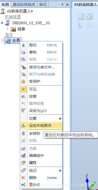
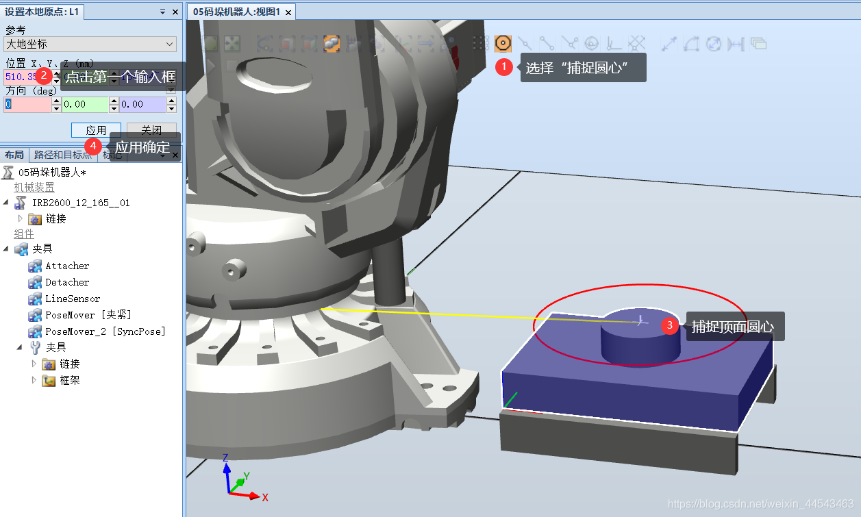
- Align the local coordinates of the gripper Smart Component with those of the robot’s end flange so that they coincide, preparing the gripper for installation in the next step.

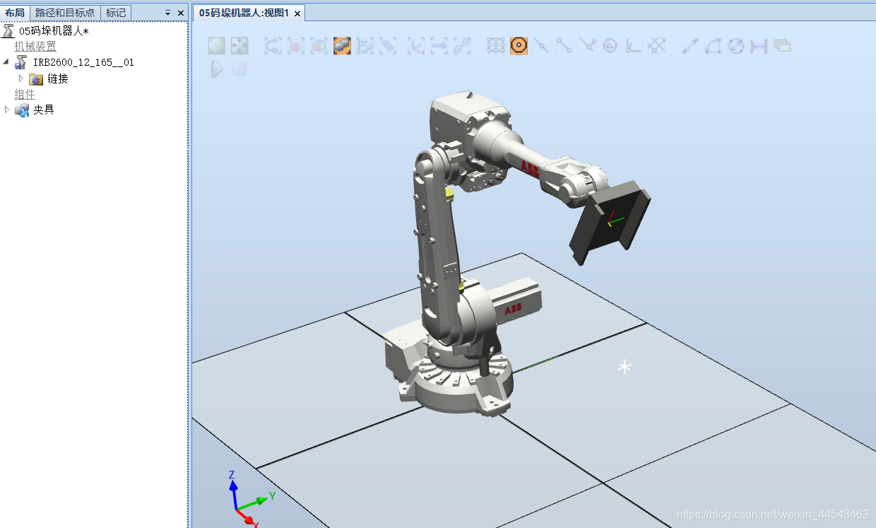
- In the Layout menu, drag the gripper onto the IRB2600 robot to complete the installation.
II. Create the Conveyor
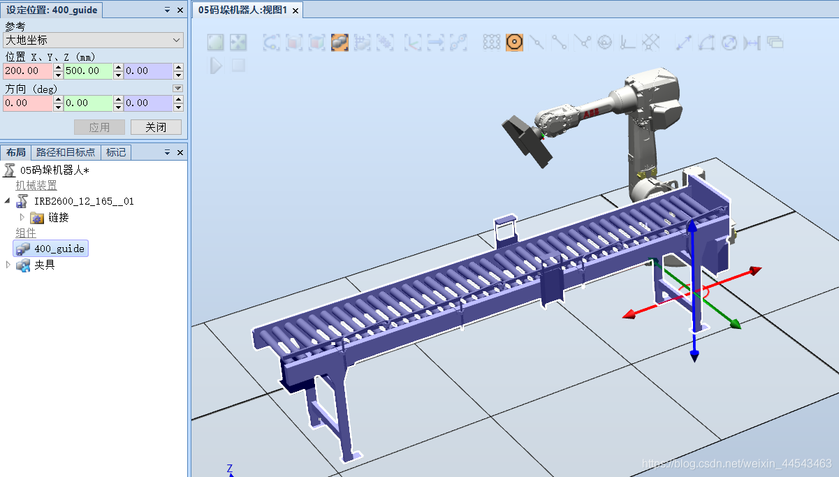
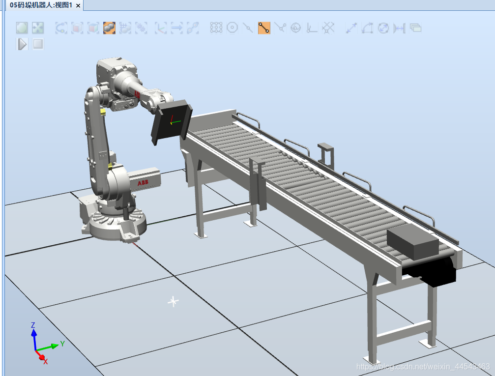
- Import the conveyor and set its position.
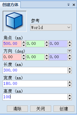
- Create the object to be palletized and move it to the beginning of the conveyor.
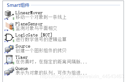
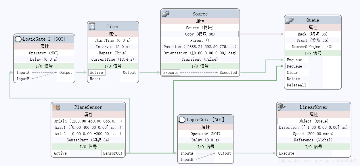
- Create a Smart Component to move objects on the conveyor. Add the following components.
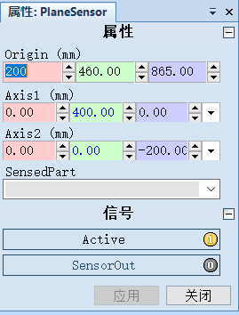
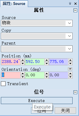
- Configure each component.


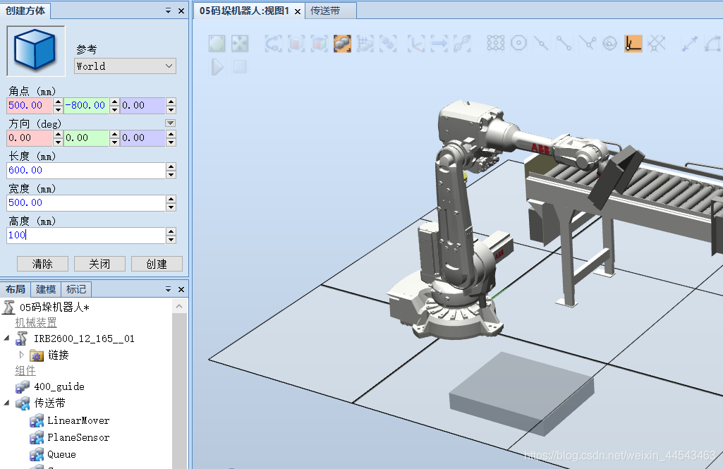
III. Create the Palletizing Base
IV. Create the Robot System
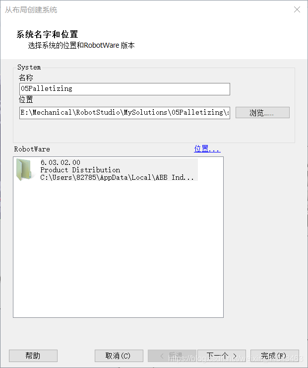
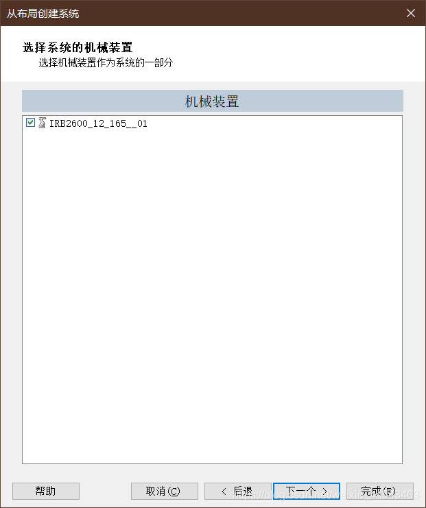 Under Options, select the following option.

V. Configure the Simulation System
-
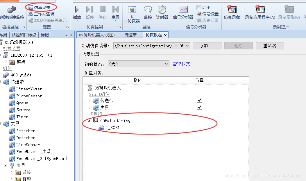
In Simulation Setup, clear the checkbox next to the robot system.
-
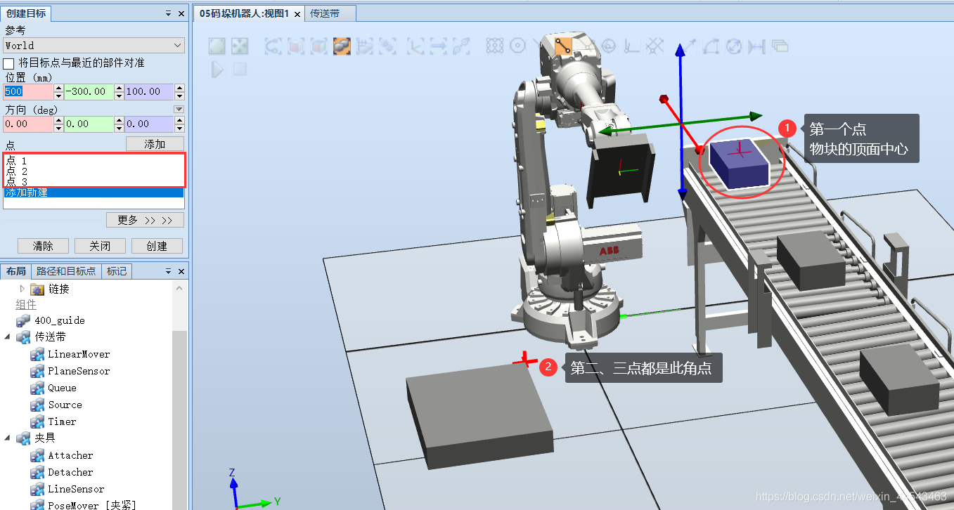
Run the simulation until the block reaches the plane sensor, then stop the simulation and capture several target points. (The last two target points are used because the blocks have two placement poses during palletizing, so two target points are required.)
-
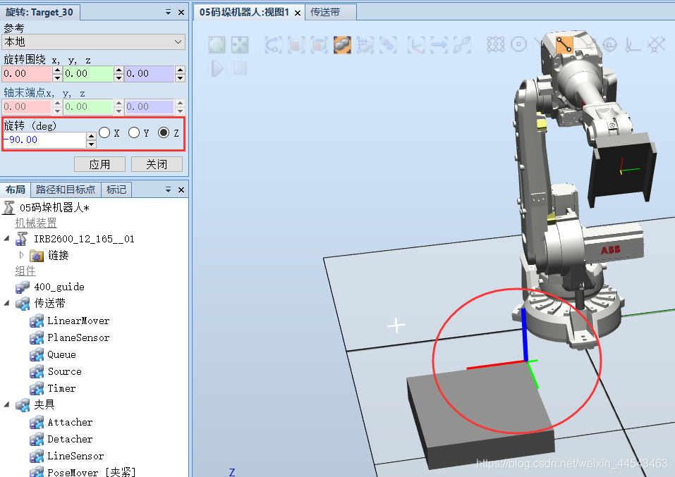
Rotate the third target point by -90 degrees about the Z-axis.
-
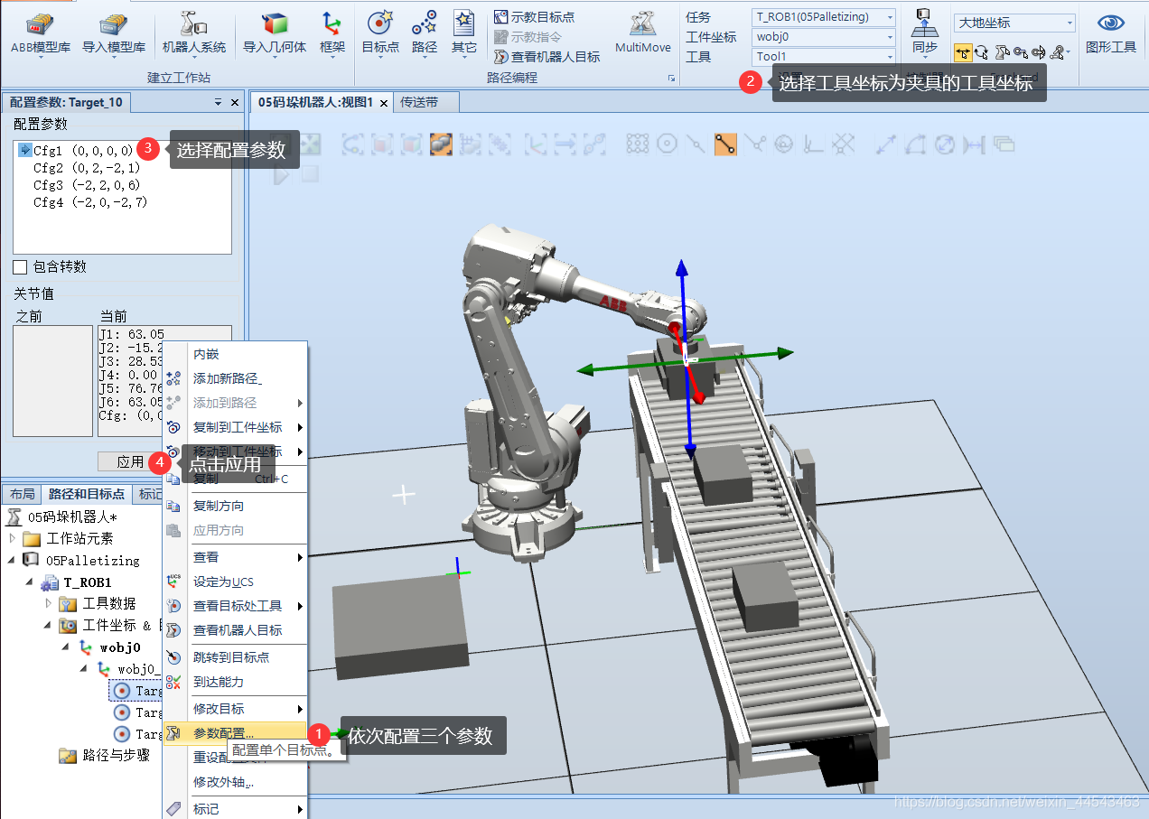
Configure the parameters for the target points.
-
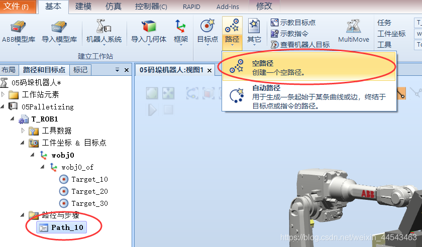
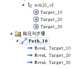
Return the robot to its mechanical home position, then create an empty path and drag the three target points into it in sequence.
-
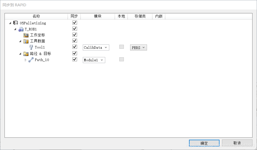
Synchronize to the station.

-
Delete the copied block created by the earlier simulation.
-
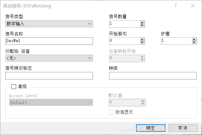
Add two signals: an in-position signal that the conveyor waits for and a gripper signal. Restart the controller after adding them.



-
Open the controller. You can see the program module under RAPID/T_ROB1 and then begin writing the program.
Program
The main program code is as follows:
MODULE Module1
	CONST robtarget Target_10:=[[347.037,682.5,875.06],[1,0,0,0],[0,0,0,0],[9E9,9E9,9E9,9E9,9E9,9E9]];
	CONST robtarget Target_20:=[[500,-300,100],[1,0,0,0],[-1,0,-1,0],[9E9,9E9,9E9,9E9,9E9,9E9]];
	CONST robtarget Target_30:=[[500,-300,100],[0,0,0,1],[-1,0,1,0],[9E9,9E9,9E9,9E9,9E9,9E9]];
	VAR num layer:=1;
    VAR num x:=0;
    VAR num z:=0;
    PROC main()
        FOR i FROM 0 TO 20 DO
            SetDO JiaJu0,0;
            MoveJ Offs(Target_10,0,0,200),v500,fine,Tool1;
            WaitDI DaoWei0,1;
            MoveL Offs(Target_10,0,0,0),v500,fine,Tool1;
            SetDO JiaJu0,1;
            WaitTime 1;
            MoveL Offs(Target_10,0,0,200),v500,fine,Tool1;

            IF layer MOD 2 = 1 THEN
                IF i MOD 5 < 4 and i MOD 5 <> 0 THEN
                    MoveL Offs(Target_30,90+x,-150,300+z),v500,fine,Tool1;
                    MoveL Offs(Target_30,90+x,-150,100+z),v500,fine,Tool1;
                    SetDO JiaJu0,0;
                    WaitTime 1;
                    MoveL Offs(Target_30,90+x,-150,300+z),v500,fine,Tool1;
                    x:=x+210;
                    IF i MOD 5 = 3 THEN
                        x:=0;
                    ENDIF
                ELSE
                    MoveL Offs(Target_20,150+x,-410,300+z),v500,fine,Tool1;
                    MoveL Offs(Target_20,150+x,-410,100+z),v500,fine,Tool1;
                    SetDO JiaJu0,0;
                    WaitTime 1;
                    MoveL Offs(Target_20,150+x,-410,300+z),v500,fine,Tool1;
                    x:=x+300;
                ENDIF
                IF i MOD 5 = 0 THEN
                    layer:=2;
                    x:=0;
                    z:=z+100;
                ENDIF

            ELSE
                IF i MOD 5 < 3 THEN
                    MoveL Offs(Target_20,150+x,-100,300+z),v500,fine,Tool1;
                    MoveL Offs(Target_20,150+x,-100,100+z),v500,fine,Tool1;
                    SetDO JiaJu0,0;
                    WaitTime 1;
                    MoveL Offs(Target_20,150+x,-100,300+z),v500,fine,Tool1;
                    x:=x+300;
                    IF i MOD 5 = 2 THEN
                        x:=0;
                    ENDIF
                ELSE
                    MoveL Offs(Target_30,100+x,-350,300+z),v500,fine,Tool1;
                    MoveL Offs(Target_30,100+x,-350,100+z),v500,fine,Tool1;
                    SetDO JiaJu0,0;
                    WaitTime 1;
                    MoveL Offs(Target_30,100+x,-350,300+z),v500,fine,Tool1;
                    x:=x+210;
                ENDIF
                IF i MOD 5 = 0 THEN
                    layer:=1;
                    x:=0;
                    z:=z+100;
                ENDIF
            ENDIF

        ENDFOR
        z:=0;
    ENDPROC
ENDMODULE
Simulation Test
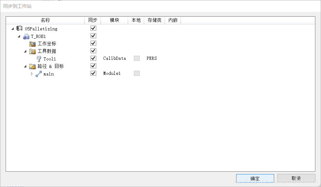
- Synchronize the code to the station.
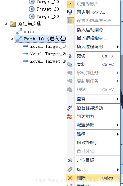
- Delete the Path_10 path, leaving only the main path.
- Configure the station logic.

- Run the simulation.
Comments